Shutter device

A shutter device and slat technology, which is applied to door/window protection devices, shutters/movable grilles, windows/doors, etc., can solve the problems of time-consuming and labor-intensive lifting of slats, and achieve convenient lifting and low weight light effect

Inactive Publication Date: 2009-03-18
OILES ECO CORP
View PDF3 Cites 0 Cited by
  • Summary
  • Abstract
  • Description
  • Claims
  • Application Information

AI Technical Summary

Problems solved by technology

[0004] In the shutter device disclosed above, since each connecting mechanism is formed by a chain-like plate-shaped steel connecting piece with several shafts, it takes time to assemble this connecting mechanism, and due to the weight of the connecting mechanism , it takes a lot of effort to raise and lower the slats

Method used


Image

  • Shutter device
  • Shutter device
  • Shutter device

Examples


Embodiment Construction

[0041] specific implementation

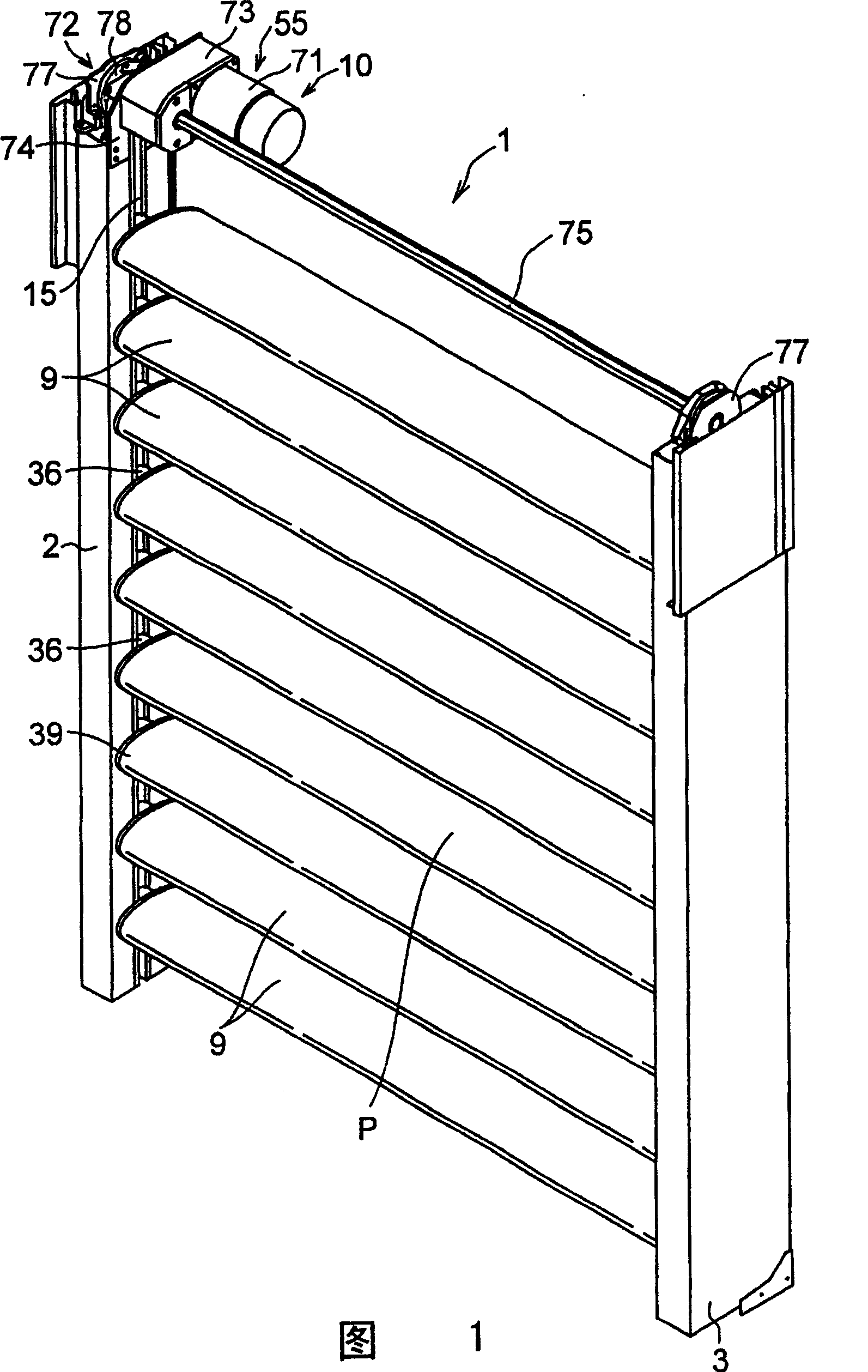
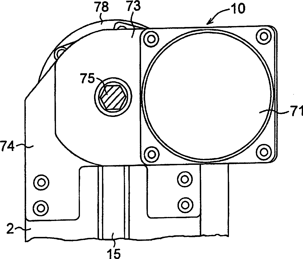
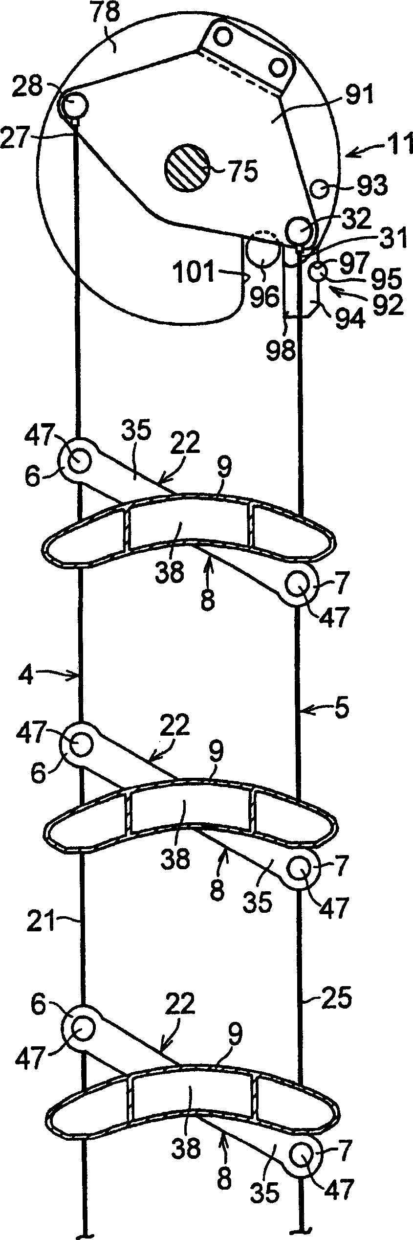
[0042] In Figures 1 to 6, a window shutter device 1 according to the present embodiment comprises a pair of mullions 2 and 3; a connecting mechanism 4; a plurality of slat supporting mechanisms 8, each of which ends 6 connected to the connecting mechanism 4, While the other end 7 is connected to the connecting mechanism 5; a plurality of slats 9, each supported by a corresponding slat supporting mechanism 8, and juxtaposed in the opening P between the mullions 2 and 3; a lifting mechanism 10 for lifting the slats 9; and a tilting mechanism 11 for tilting the respective respective slats by subjecting the connecting mechanisms 4 and 5 to relevant changes in their vertical positions when the lifting mechanism 10 raises or lowers the slats. slats9.

[0043]The hollow mullion 2 has a guide groove 15 extending vertically, and the hollow mullion 3 also has a guide groove 16 extending vertically. The connecting mechanisms 4 and 5 and the tilting me...


PUM


Abstract

To provide a blind device which allows the assembling of link mechanisms in a short time, reduces weights of the link mechanisms, and facilitates the lifting/lowering of slats without requiring so-large power. The blind device 1 is formed of a pair of vertical frames 2, 3, the link mechanisms 4, 5 arranged in parallel, a plurality of slat support mechanisms 8, a plurality of slats 9, a lifting/lowering mechanism 10, and a tilt mechanism 11. Each slat support mechanism 8 has one end 6 connected to the link mechanism 4 and the other end 7 connected to the link mechanism 5. The slats 9 are supported by the slat support mechanisms 8 and arranged in an opening P between the vertical frames 2, 3 in parallel with each other. The lifting/lowering mechanism 10 functions to lift/lower the slats 9. The tilt mechanism 11 causes a relative vertical locational change between the link mechanisms 4, 5 at the time of lifting/lowering the slats 9 by the lifting/lowering mechanism 10, to thereby tilt the slats 9. (C)2004,JPO.

Description

technical field [0001] The present invention relates to a shutter arrangement for opening or closing an opening such as a building window. Background technique [0002] The present attorney previously disclosed a shutter device in JP-A-8-326445. [0003] The shutter device includes a pair of connecting mechanisms; a plurality of slat supporting mechanisms, each of which has one end connected to one of the connecting mechanisms and the other end connected to the other connecting mechanism; a plurality of slats; a lift mechanism for raising and lowering the slats; and a tilting mechanism for tilting each slat by causing a relative change in position of a pair of connecting mechanisms as the slats are raised and lowered by the lift mechanism. Each of said slat support mechanisms has an arm member for supporting an end portion of said slat at a substantially central portion of an arm member. [0004] In the shutter device disclosed above, since each connecting mechanism is for...

Claims


Application Information

Patent Timeline
Patent Type & Authority Patents(China)
IPC IPC(8): E06B9/02E06B7/086E06B9/322
CPCE06B7/086E06B9/0638E06B9/0676E06B9/02
Inventor 大石守松本浩司中岛广成
Owner OILES ECO CORP
Why Eureka
Try Eureka