Selective protection switch

A protection switch and selective technology, which is applied in the direction of protection switch operation/release mechanism, etc., can solve the problems of no short-circuit short-time delay protection characteristics, inability to selectively protect terminal electrical equipment, and affecting the stability and reliability of power supply systems, etc. , to achieve the effect of solving the problem of leapfrog tripping

Active Publication Date: 2009-04-08
SEARI ELECTRIC TECH +2
View PDF2 Cites 0 Cited by
  • Summary
  • Abstract
  • Description
  • Claims
  • Application Information

AI Technical Summary

Problems solved by technology

[0002] At present, with the development of building electrical and building automation, miniature circuit breakers are more and more widely used in residential power distribution systems, but because most of these switches lack selective protection functions (only Section protection characteristics, but no short-circuit short-time delay protection characteristics), which leads to the phenomenon of leapfrog tripping in the residential power distribution system, which greatly affects the stability and reliability of the power supply system
Although the front-connected fuse can provide the necessary short-circuit backup protection, it cannot provide the necessary selective protection for the terminal electrical equipment, so there is an urgent need for corresponding products to realize such functions, so as to make the terminal power distribution system more stable and reliable

Method used


Image

  • Selective protection switch
  • Selective protection switch
  • Selective protection switch

Examples


no. 1 example

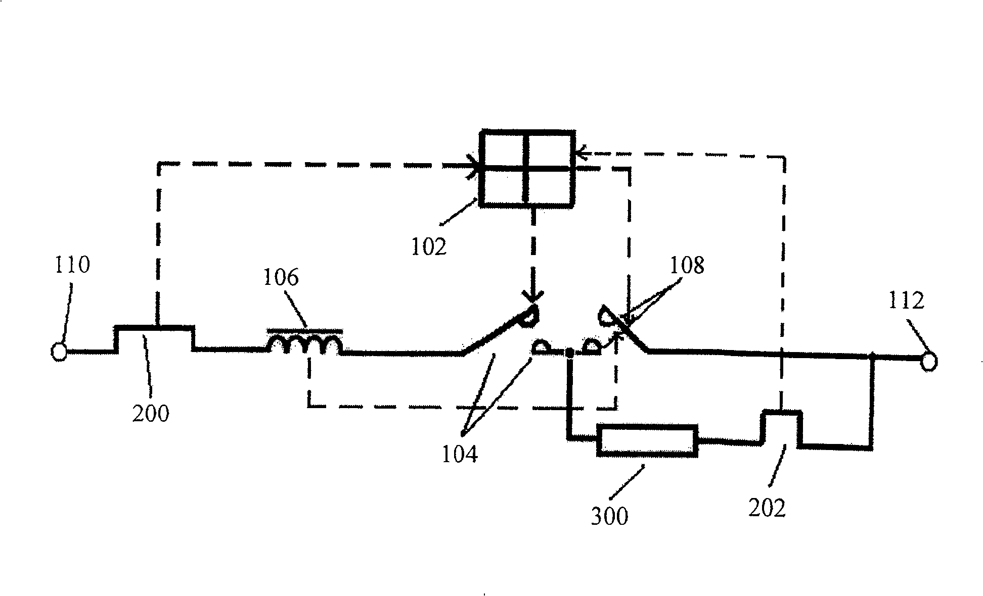
[0036] refer to figure 2 , according to the first embodiment of the present invention, the tripping device 100 includes a first overcurrent release 200 and a second overcurrent release 202, wherein one end of the first contact 104 is connected to the electromagnetic mechanism 106, and the electromagnetic mechanism 106 also Connect to one end of the first overcurrent release 200, the other end of the first overcurrent release 200 is connected to the first connection terminal 110, the other end of the first contact 104 and one end of the second contact 108 jointly form a pair Contact structure, the second contact 108 is also connected to the second terminal 112, a current limiting resistor 300 is connected in series with the second overcurrent release 202 and connected in parallel at both ends of the second contact 108, the single operating mechanism 102 Connected with the first and second overcurrent releases 200 and 202, and act on the first and second contacts 104 and 108 to...

no. 2 example

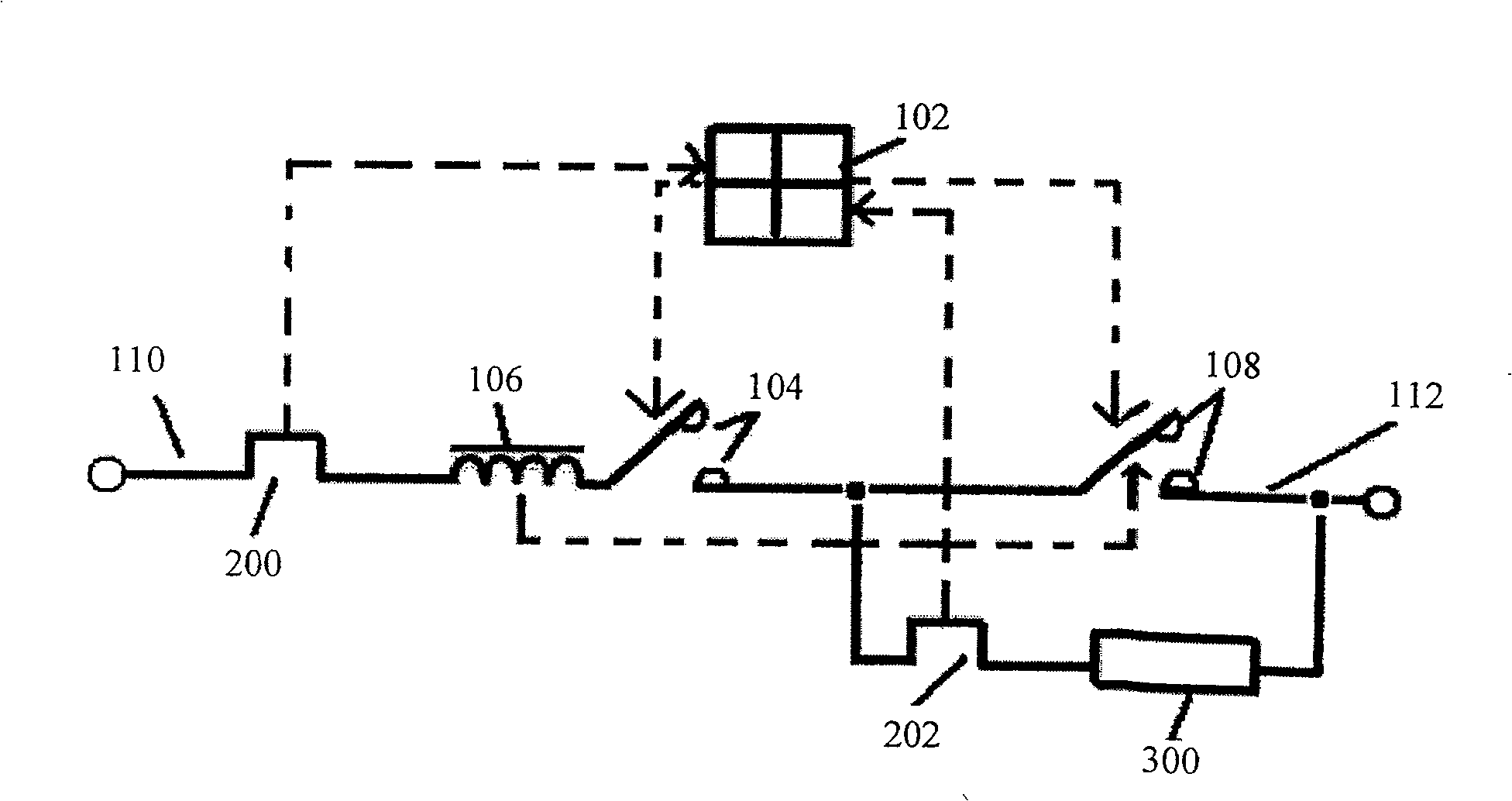
[0038] refer to image 3 , which shows a second embodiment of the invention, which is compatible with figure 2 The difference in the illustrated embodiment is that the first contact 104 and the second contact 108 are two single contacts in series, rather than like figure 2 A double contact structure is formed as in the first embodiment shown. At the same time, the positions of the second overcurrent release 202 and the current limiting resistor 300 connected in series are exchanged.

no. 3 example

[0040] refer to Figure 4 , which shows a third embodiment of the invention, which is the same as figure 2 The difference of the illustrated exemplary embodiment is that the positions of the first overcurrent release 200 and the electromagnetic mechanism 106 connected in series are reversed.

[0041] In summary, with the first implementation, the devices connected in series on the same current branch can exchange positions, and the two contacts can also be connected in different ways. These are all within the protection scope of the present invention. At the same time, it should be noted that the first contact 104 and the second contact 108 , the first overcurrent release 200 and the second overcurrent release 202 , and the first connection terminal 110 and the second connection terminal described here are 112 are equivalent concepts, that is, the first connection terminal 110 may be an incoming line end or an outgoing line end, and correspondingly, the second connecting te...


PUM


Abstract

The invention proclaims a selective switch, comprising a releasing device, an operating mechanism, a first contact, an electromagnetic mechanism and a second contact, where the operating mechanism controls the two contacts according to releasing signal of the releasing device, and the electromagnetic mechanism controls the second contact. The selective switch makes up for the insufficiency that the micro breaker in terminal power distribution network is short of selective protecting functions and provides a way of being able to solve the skip tripping problem between higher-level and lower-level switches to a certain extent.

Description

technical field [0001] This invention relates to electrical protection devices, and more particularly to selective protection switches for use in terminal power distribution networks. Background technique [0002] At present, with the development of building electrical and building automation, miniature circuit breakers are more and more widely used in residential power distribution systems, but because most of these switches lack selective protection functions (only Section protection characteristics, but no short-circuit short-time delay protection characteristics), which leads to the phenomenon of leapfrog tripping in the residential power distribution system, which greatly affects the stability and reliability of the power supply system. Although front-connected fuses can provide the necessary short-circuit backup protection, they cannot provide the necessary selective protection for terminal electrical equipment. Therefore, corresponding products are urgently needed to ...

Claims


Application Information

Patent Timeline
Patent Type & Authority Patents(China)
IPC IPC(8): H01H71/24H01H71/16
Inventor 陈颖刘城龚骏昌陈黎俊
Owner SEARI ELECTRIC TECH
Why Eureka
Try Eureka