Disposable safety self-breaking injector
A disposable, syringe technology, applied in the field of medical equipment, can solve the problems of increasing the workload of medical staff and complicated operation, and achieve the effect of simple structure, convenient operation and safe use
- Summary
- Abstract
- Description
- Claims
- Application Information
AI Technical Summary
Problems solved by technology
Method used
Image
Examples
Embodiment 1
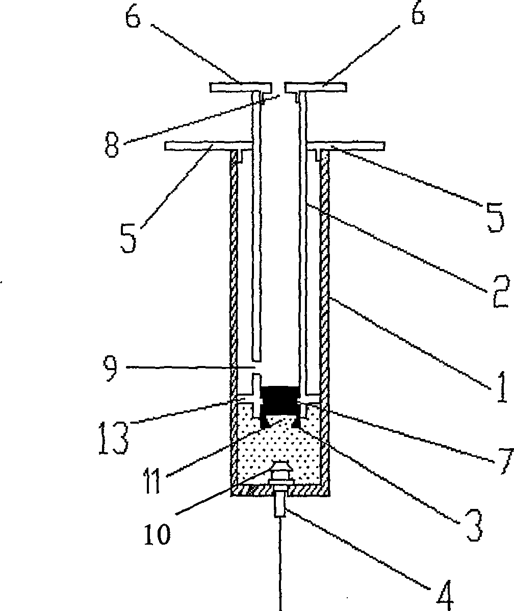
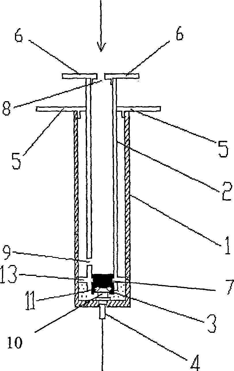
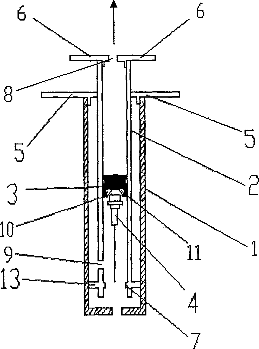
[0026] Such as figure 1 , figure 2 , image 3 , Figure 5 , Figure 6 shown. The structure for making a disposable safe self-destructing syringe includes a hollow syringe 1, a push rod 2 that can slide in the syringe 1, a rubber stopper 3 stuck on the front end of the push rod 2, and a detachable assembly at the front end of the syringe 1. The needle holder 4 , the needle head assembled at the front end of the needle holder 4 , the sealing member A 5 , and the sealing member B 6 . There is a hole in the middle of the sealing member A 5, which is assembled at the afterbody of the syringe 1. The size of the hole is equal to the outer diameter of the push rod 2 shaft, so that the sealing member can be passed through the shaft of the push rod 2 during assembly. A 5 is assembled at the tail of the syringe 1, and after being assembled, it can be in close contact with the shaft of the push rod 2 and can make the shaft of the push rod 2 slide up and down through the sealing memb...
Embodiment 2
[0029] Such as Figure 4 , Figure 7 , Figure 8 shown. The same content as in Embodiment 1 will not be repeated, the difference is:
[0030] The size of the opening in the middle of the sealing member A 5 at the afterbody of the syringe 1 is slightly smaller than the outer diameter of the push rod 2 shaft. The outer diameter of the outer edge 13 is slightly larger than the inner diameter of the syringe 1 . The inward protrusions 7 of the push rod 2 are two symmetrical clips. The shape of the rubber plug 3 is that there are two symmetrical bayonets with the shape and size corresponding to the clips in the middle, so that the rubber plug 3 can be just stuck on the protrusions 7. , and can seal the liquid or gas at the front end of the syringe 1 from entering the push rod 2. The longitudinal cross-section of the groove 11 of the rubber stopper 3 is T-shaped, and the depth of the groove 11 is equal to the height of the needle base 4 in the syringe 1, so that the rubber stopp...
Embodiment 3
[0032] The same content as in Embodiment 1 will not be repeated, the difference is that: the inward protrusion 7 of the push rod 2 is 4 evenly distributed clips, and the shape of the rubber plug 3 is that there are 4 shapes and sizes in the middle that are similar to the clips The corresponding uniform bayonet can make the rubber stopper 3 just be stuck on the protrusion 7 . The depth of the groove 11 is greater than the height of the needle seat 4 inside the syringe 1, so that the rubber stopper 3 can be pushed inwardly towards the push rod 2 by the force of the front end of the syringe 1 during use.
PUM
 Abstract
Description
Claims
Application Information
 - R&D
- Intellectual Property
- Life Sciences
- Materials
- Tech Scout
- Unparalleled Data Quality
- Higher Quality Content
- 60% Fewer Hallucinations
Browse by: Latest US Patents, China's latest patents, Technical Efficacy Thesaurus, Application Domain, Technology Topic, Popular Technical Reports.
© 2025 PatSnap. All rights reserved.Legal|Privacy policy|Modern Slavery Act Transparency Statement|Sitemap|About US| Contact US: help@patsnap.com


