
Synchronous digit transmission equipment and method thereof

A technology for synchronizing digital and transmission equipment, applied in digital transmission systems, transmission systems, synchronization devices, etc., can solve problems such as waste of resources, inability to expand, and inability to use the bus, and achieve the goal of maintaining forward compatibility and improving service access capabilities Effect

Inactive Publication Date: 2009-04-29
HUAWEI TECH CO LTD
View PDF3 Cites 0 Cited by
  • Summary
  • Abstract
  • Description
  • Claims
  • Application Information

AI Technical Summary

Problems solved by technology

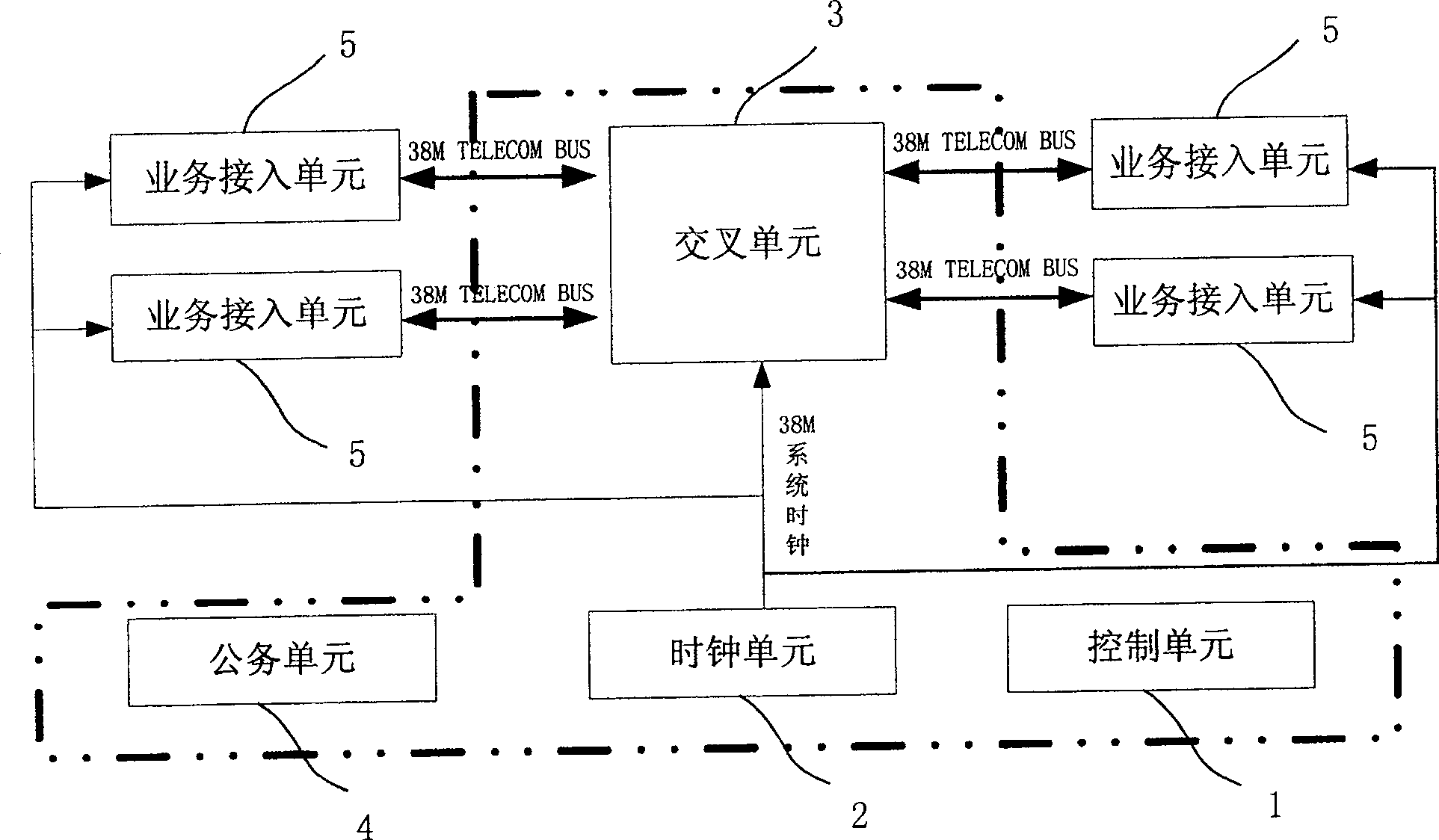
At present, the service bus of SDH equipment (synchronous digital transmission equipment) generally adopts the communication bus (Telecom Bus), and the bus frequency can be 38M or 77M, and the frequency of the communication bus is fixed and cannot be changed, so each service access unit 5 The bandwidth is also fixed (that is, the access capacity is also fixed), and cannot be expanded
With the development of telecommunication services, the access bandwidth of optical transmission equipment is required to increase, so only the development of new optical transmission equipment can meet the requirements. Generally, the method of increasing the bus frequency is used to increase the access capacity of each service access unit 5 , For example, use a higher rate low voltage differential signaling (LVDS, Low Voltage Differential Signaling) bus, but after doing so, the boards of various low rate buses developed in the past cannot be used on new equipment, while the high rate The bus cannot be used on old equipment, which caused customers to waste investment and resources in the past

Method used


Image

  • Synchronous digit transmission equipment and method thereof
  • Synchronous digit transmission equipment and method thereof
  • Synchronous digit transmission equipment and method thereof

Examples


Embodiment Construction

[0021] Please refer to figure 2 As shown, for the low-end synchronous digital transmission equipment in the access layer, 38M Telecom Bus is generally used to connect the cross unit and the service access unit. The 38M Telecom Bus uses 4 connections to transmit a STM-1 (Synchronous Transfer Mode, synchronous transfer mode) signal, that is, a signal with a frequency of 155M. In this way, 4 business buses are connected as a group. When the frequency of the business bus is 38M (for example, using 38M Telecom Bus), a bus bandwidth of STM-1 (155M) can be provided; if the speed of the business bus is increased to 77M, it can be Provides 2 STM-1 bus bandwidth (such as image 3 shown). Similarly, if the electrical connection is permitted, the service bus rate can continue to increase, so that under the same physical connection, the service bandwidth that can be transmitted is improved, that is, the access capability of synchronous digital transmission equipment is enhanced.

[002...


PUM


Abstract

The sync digital transmission equipment includes cross unit creating connection to the service access unit via the service bus to complete the service dispatching between service access units, clock unit providing the system with sync clock, and control unit controlling the cross unit and the clock unit to complete the system configuration and monitoring. The cross unit includes bus operation mode in at least one frequency, the clock unit provides at least one clock frequency backing up sync clock bus operation mode, and the control unit identifies information based on the bus rate the service access unit connected to the cross unit and allocates the service access unit, the cross unit with corresponding sync clock and selects corresponding bus operation mode. The present invention also discloses corresponding sync digital transmission method. The sync digital transmission equipment and method can raise bandwidth access capacity on the basis of traditional SDH or SONET equipment while maintaining forward compatibility.

Description

technical field [0001] The invention relates to optical transmission equipment in communication technology, especially a synchronous digital transmission (SDH, Synchronous Digital Hierarchy or SONET, Synchronous Optix Network) equipment and method. Background technique [0002] In the mid-1980s, optical fiber communication began to be widely used in communication networks, mainly focusing on point-to-point transmission and adopting a quasi-synchronous (PDH) transmission system. With the gradual formation and expansion of the optical fiber trunk network, users and services are constantly increasing. However, the PDH transmission system without uniform standard optical interface, incompatible with multi-vendor equipment, and limited transmission rate is obviously inconsistent with the development trend of optical fiber communication. [0003] For this reason, Bell Communication Research Institute of the United States proposed the concept of optical synchronous transmission net...

Claims


Application Information

Patent Timeline
Patent Type & Authority Patents(China)
IPC IPC(8): H04L12/40H04L7/00
Inventor 雷敏
Owner HUAWEI TECH CO LTD
Learn More