

Vehicle seat lock
A seat lock and car body technology, applied in the field of car seat locks, can solve problems such as quality degradation
- Summary
- Abstract
- Description
- Claims
- Application Information
AI Technical Summary
Problems solved by technology
Method used
Image

Examples
Embodiment Construction
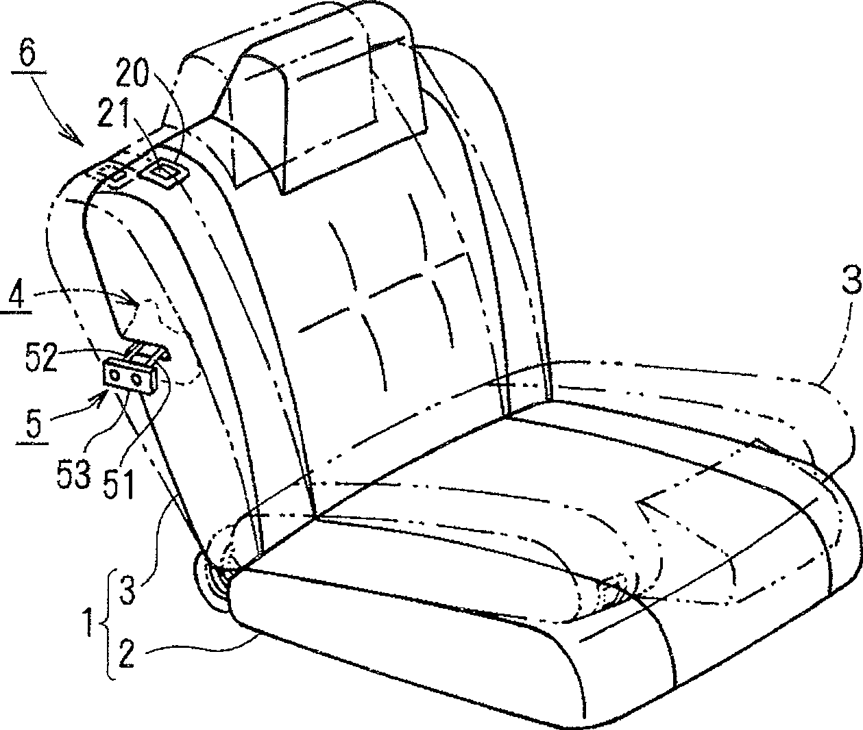
[0026] Such as figure 1 As shown, the rear seat 1 includes a seat cushion 2 and a seat back 3, the seat cushion 2 is installed on the vehicle body floor, and the seat back 3 is supported by a hinge shaft (not shown) at the rear end of the seat cushion 2 to enable It collapses onto the seat cushion 2.
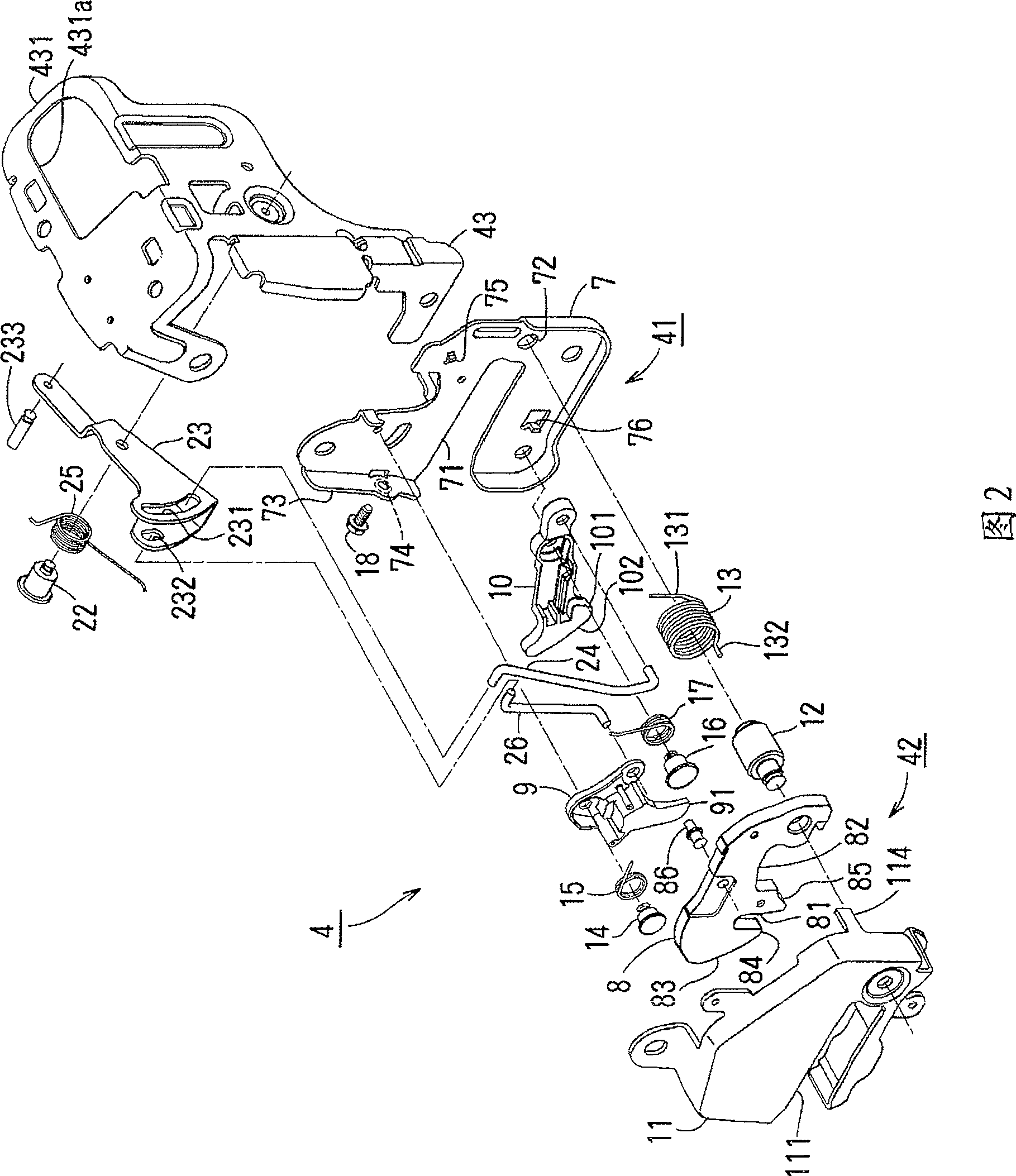
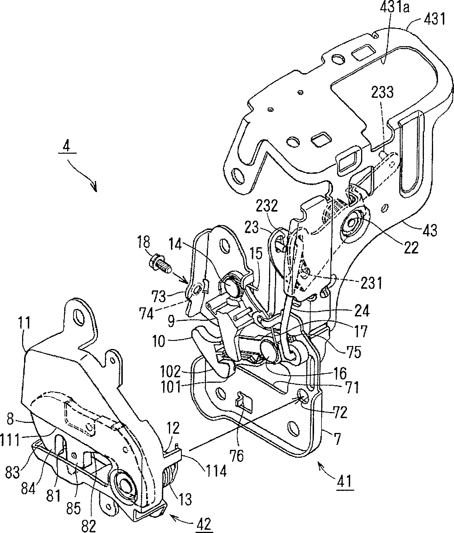
[0027] In the seat back 3, the locking assembly 4 is arranged under the shoulder, close to the vehicle body panel, and the locking assembly 4 is engaged with the metal striker 5 fixed on the vehicle body panel, so that the seat back 3 can be held in a solid position. The first upright position shown by the line and the second upright position shown by the dotted line tilted backward from the first upright position, and the seat back can be positioned at the operating device 6 in the shoulder of the seat back 3 by operating And put it forward.
[0028] The striker 5 includes: a base portion 53 fixed to a vehicle body panel on a side facing the seat back 3 ; and a U-shaped engag...
PUM
 Abstract
Description
Claims
Application Information