Connector

一种连接器、连接部的技术,应用在连接、连接装置的零部件、固定/绝缘接触构件等方向,能够解决部件数量增大、组装工序数增加、基板占有面积增大等问题,达到防止触点脱落、提高校准精度、准确定位的效果

Active Publication Date: 2013-08-21
JST MFG CO LTD
View PDF10 Cites 7 Cited by
  • Summary
  • Abstract
  • Description
  • Claims
  • Application Information

AI Technical Summary

Problems solved by technology

However, there is a problem that the number of parts increases when an adjustment board is used in the connector
Furthermore, due to the increase in the number of components, the number of assembly steps is also increased, and the occupied area on the board is increased, and there is also a problem that miniaturization and space saving of the connector cannot be achieved.
Also, when the adjustment plate is used, when the connector vibrates, the adjustment plate comes into contact with the contacts, and cutting impurities may be generated to cause malfunctions in the connector and other equipment
Furthermore, when the contacts are mounted on the substrate by soldering, when a temperature change occurs in the device, a stress load is applied to the soldered part due to the difference in the linear expansion coefficient of the adjustment board and the substrate, and, in the solder Cracks that may cause poor connection of the contacts to the substrate

Method used


Image

  • Connector
  • Connector
  • Connector

Examples


Embodiment approach 1

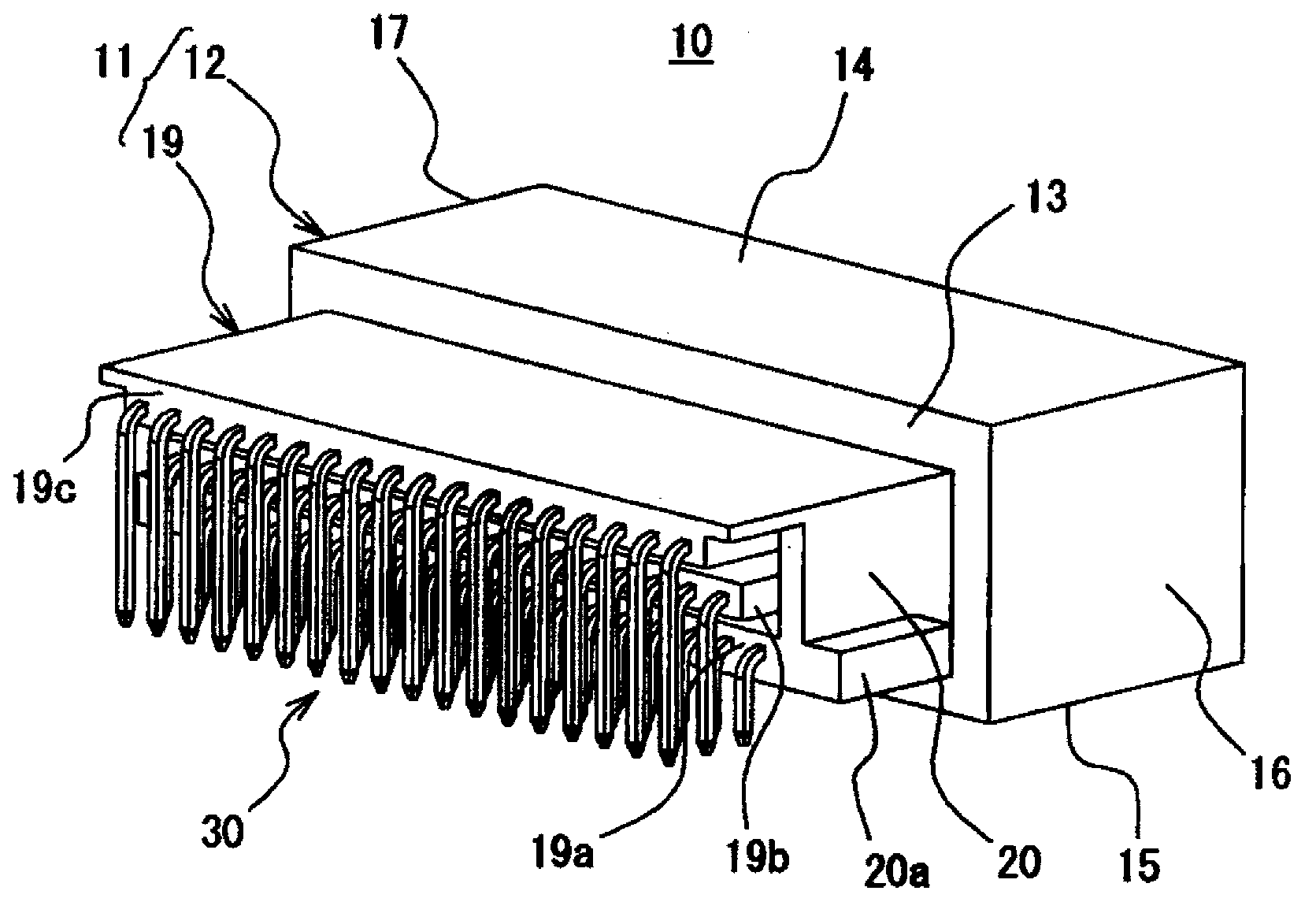
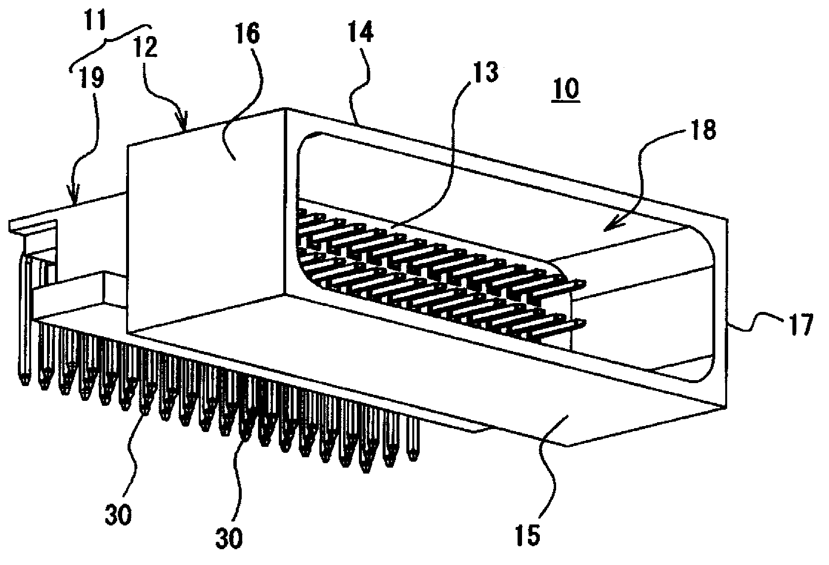
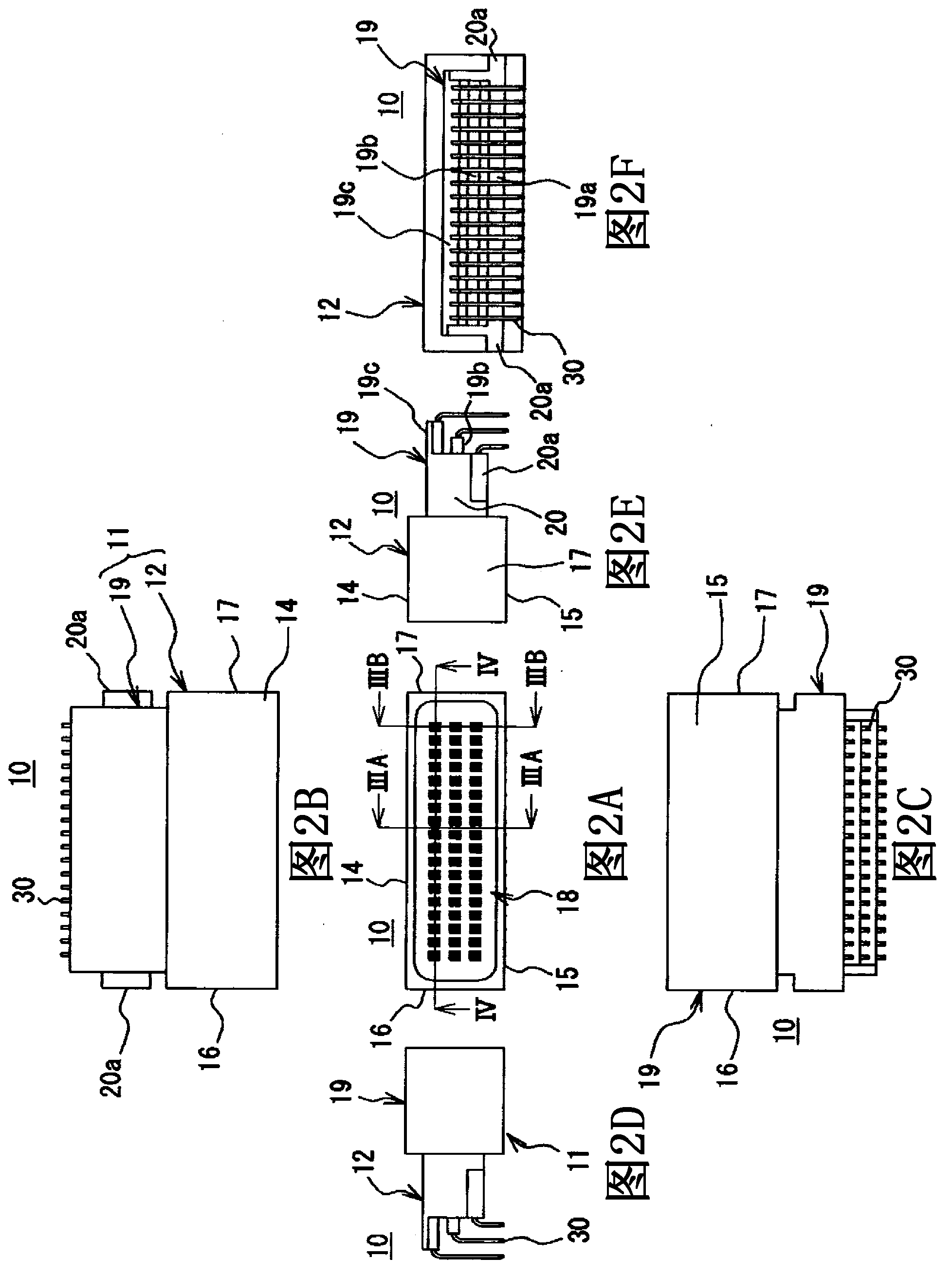
[0048] refer to Figure 1A ~ Figure 8B The connector of Embodiment 1 will be described. Such as Figure 1A , Figure 1B and Figure 2A-Figure 2F As shown, the connector 10 according to Embodiment 1 is constituted by a housing 11 formed of an insulating material, and a plurality of contacts 30 mounted on the housing 11 . In addition, the connector 10 of Embodiment 1 is a so-called side-type connector 10 in which the direction of the contacts 30 mounted on the housing 11 is parallel to the substrate 36 (see Figure 8A , Figure 8B ), therefore, the later-described end portion of the contact 30 is bent and formed at a substantially right angle so as to be perpendicular to the substrate 36 . In addition, in the connector 10 of Embodiment 1, the structure in which the contacts 30 are arranged in three rows will be described. Next, each configuration will be described.

[0049] The housing 11 of Embodiment 1 is composed of a fitting part 12 for fitting with a counterpart conne...

Embodiment approach 2

[0073] refer to Figure 9 ~ Figure 13B A connector according to Embodiment 2 will be described. In the connector of Embodiment 1, a so-called side-type connector was described, but the connector of Embodiment 2 is a so-called peak-type connector mounted vertically with respect to the board. In addition, in the connector of Embodiment 2, compared with the connector of Embodiment 1, only the shape of a part of the housing and the contacts is different, and the other parts are the same. Therefore, the same structure as the connector of Embodiment 1 The same reference numerals are attached, and detailed explanations are omitted.

[0074] Such as Figure 9 and Figure 10A-Figure 10C As shown, a connector 10A according to Embodiment 2 is composed of a housing 11A formed of an insulating material, and a plurality of contacts 30A mounted on the housing 11A. In addition, connector 10A of Embodiment 2 demonstrates the case where contacts 30A are aligned in a row. Furthermore, the c...


PUM


Abstract

Provided is a connector which can improve alignment accuracy of the contacts without using a compensation plate and has a small number of components. The connector includes a housing (11) with a plurality of contacts (30). The housing (11) possesses an assembling part (12) and a holding part (19)extending from the assembling part (12). Each of the contacts (30) includes a leading end (31), a connecting part (32), a held part (34), and a flange part (33). The housing (19) has a contact insertion hole (21) into which the held part (34) is inserted. The contact insertion hole (21) includes: a first insertion hole (24) in which a side surface of the held part (34) of the contact (30) is held; a second insertion hole (25) formed in a size that holds one opposite side surface of the held part (34) of the contact (30), and having a space on the other opposite side surface side, the second insertion hole (25) being formed to be longer than the first insertion hole (24); and a flange holding part (27). The held part (34) of the contact (30) is made longer than the leading end (31) of the contact (30).

Description

technical field [0001] The present invention relates to a connector having a plurality of contacts mounted on a substrate. connectors for calibration accuracy. Background technique [0002] For example, connectors are used to connect electronic control devices and other electronic devices installed in vehicles such as automobiles. However, with the development of multi-function and high-performance electronic equipment in recent years, the miniaturization and space-saving of the equipment itself have developed, and the number of contact terminals provided in the connector has increased. The occupied area on the board with the connector is reduced, and the arrangement of the contact terminals is compact. [0003] This type of connector generally consists of a housing, contact terminals, and an adjustment plate (also known as a positioner, a tip plate.). The adjustment plate is used to improve the alignment accuracy of the end portion of the contact terminal on the substrat...

Claims


Application Information

Patent Timeline
Patent Type & Authority Applications(China)
IPC IPC(8): H01R13/40H01R13/46
CPCH01R12/724H01R12/727H01R13/41H01R13/516
Inventor 白石诚林健太郎
Owner JST MFG CO LTD
Why Eureka
Try Eureka