Quenching mechanism of steel ball quenching machine

A quenching machine and steel ball technology, applied in quenching devices, furnaces, heat treatment equipment, etc., can solve the problems of poor physical properties of steel balls, inability to adapt to receive quenching medium separately, easy to deform and replace steel balls, etc., and achieve consistent quenching time. Effect

Inactive Publication Date: 2009-06-10
CHANGSHU FEIFAN METALWORK
View PDF3 Cites 40 Cited by
  • Summary
  • Abstract
  • Description
  • Claims
  • Application Information

AI Technical Summary

Problems solved by technology

The more important reasons for affecting the quenching effect are: First, the structure of the cylinder body 8 determines that the temperature of the quenching medium in the cylinder cavity cannot be controlled, and the temperature of the quenching medium introduced into the cylinder cavity from the pipeline 84 will soon rise , because the structure of the cylinder body 8 determines that the cylinder cavity is connected, which cannot meet the requirement of receiving quenching medium separately, so it is difficult to guarantee the quenching quality of the steel balls. During use, the steel balls are poor in wear resistance and easy to wear due to their low hardness. The deformation will bring frequent replacement of steel balls to the production industry, increase the cost of use, and affect the normal production due to the low efficiency of ball milling due to deformation; second, it cannot ensure that each steel ball can obtain the same quenching time. , the steel balls that enter the cylinder cavity later will inevitably exit the cylinder cavity first, so the hardness of the same batch of steel balls after quenching is not the same
In terms of quenching efficiency, if a large number of balls are continuously fed into the cylinder cavity of the cylinder body 8 through the feeding ball lane 83, the physical properties of the steel balls will be worse due to the serious pile-up. On the contrary, if the balls are fed one by one, then Not only will the medium used for quenching be wasted, but also it will cause inactive consumption of energy, because the cylinder 8 is passively in a state of being hungry and tending to run dry

Method used


Image

  • Quenching mechanism of steel ball quenching machine
  • Quenching mechanism of steel ball quenching machine
  • Quenching mechanism of steel ball quenching machine

Examples


Embodiment 1

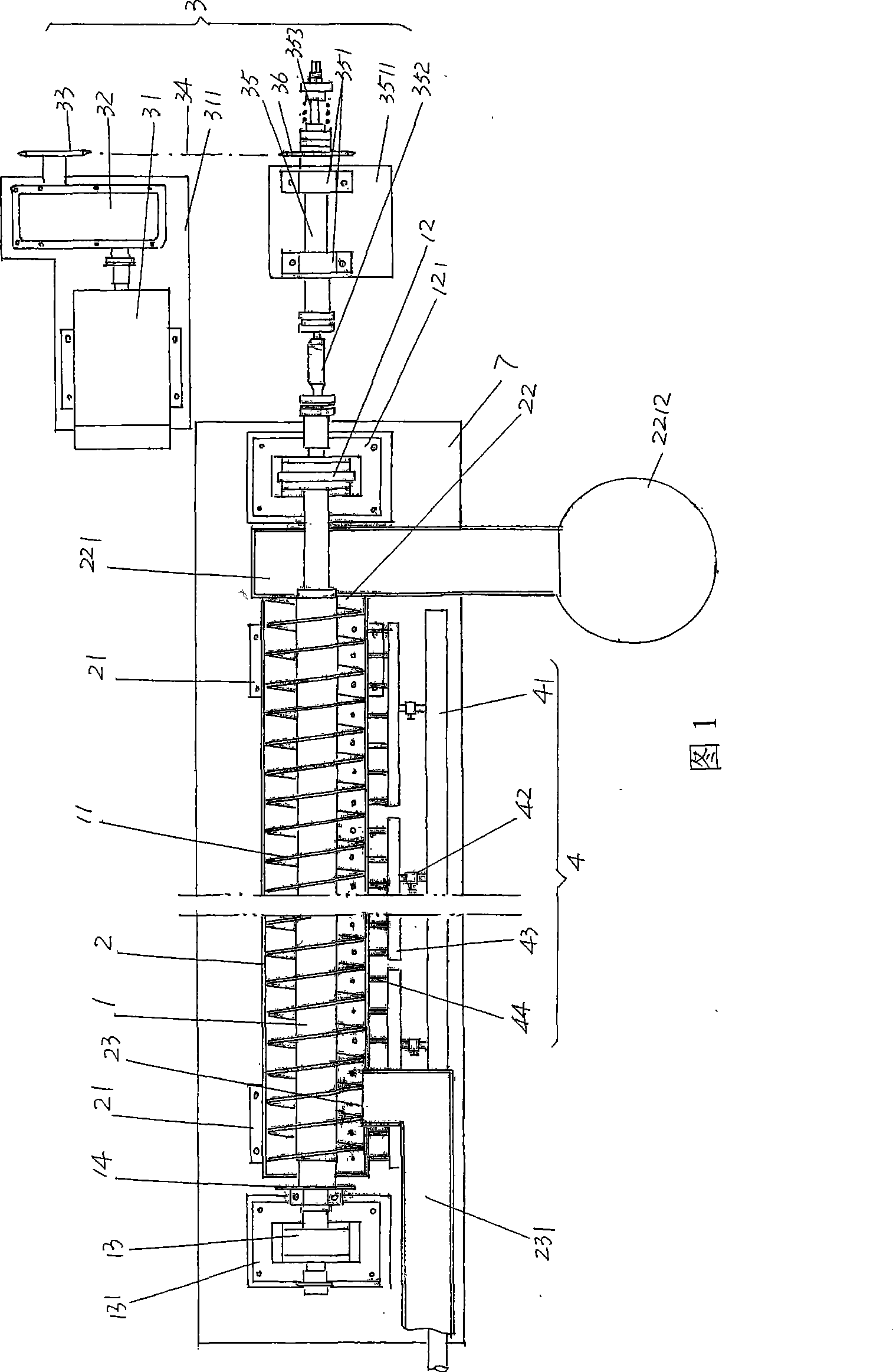
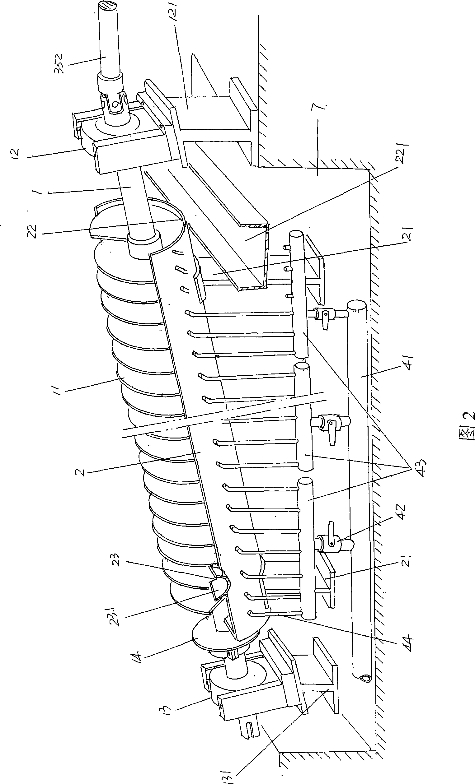
[0025] Please refer to Fig. 1 and Fig. 2, as a preferred example, the middle part of the rod body of the screw rod 1 of the quenching mechanism of the steel ball quenching machine is integrally provided with a spiral piece 11 for separating the steel balls and acting as a drive to drive the steel balls away. The distance between adjacent helical pieces 11 should meet the size (diameter) of the steel balls, so that the steel balls can be movably located therebetween. Taking the current illustrated position state as an example, the two ends of the screw rod 1, that is, the right and left ends are respectively supported on the first and second bearing supports 121, 131 through the first and second bearing supports 12, 13, and the first 1. The second bearing brackets 121 and 131 are fixed on the medium collection tank 7 at the use site of the steel ball quenching machine, and the two keep corresponding, that is, the two are on the same straight line. Among them: the first bearing ...

Embodiment 2

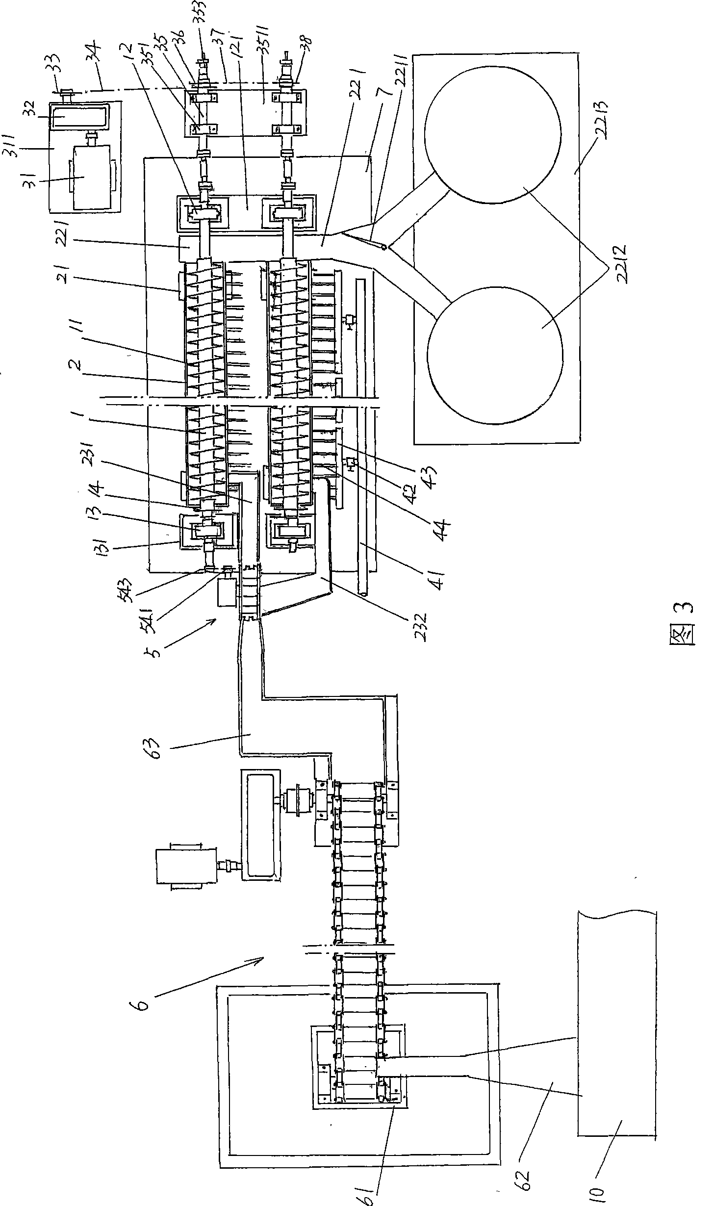
[0029] Please refer to Figure 3. Compared with Embodiment 1, the quenching mechanism of the steel ball quenching machine has two sets of the same structure and the same way. The medium conveying mechanism 4 just increases to two sets, and increases one and is used to provide the goal raceway 232 of steel ball to the medium groove 2 of a set of quenching mechanism in the front of the illustrated position state, and, second sprocket wheel 36 changes With double sprockets, increase the second chain 37 and the third sprocket 38, the second chain 37 takes on the transmission connection between a pair of main shafts 35 of two sets of quenching mechanisms. Because it is two sets of quenching mechanisms, the quenching effect will be significantly improved. Therefore, a guide door 2211 is pivotally arranged on the channel of the ball-out raceway 221 fixed on the first bearing bracket 121. When one of the pair of ball-collecting containers 2212 After a container is full of steel balls, ...

Embodiment 3

[0031] Please refer to Fig. 4 and in conjunction with Fig. 3, the structure of the ball feeding mechanism 5 suitable for the situation of embodiment 2 has been provided, the ball feeding mechanism 5 includes a first frame 51, a second speed reducer 52, a ball feeding plate 53, The power transition device 54, the second speed reducer 52 is fixed on the first frame 51, the ball feeding disc 53 is fixed on the power output shaft of the second speed reducer 52, and there is at least an intermediate spacer on the edge of the ball feeding disc 53. In response to the ball storage cavity 531 in the middle of the steel ball from the steel ball lifting mechanism 6 of the steel ball quenching machine, the power transition device 54 includes the fourth and fifth sprockets 541, 543 and the third chain 542, the fourth sprocket 541 is fixed on the shaft end of the power input shaft of the second reducer 52 , while the fifth sprocket 543 is fixed on the end of the screw rod 1 , and the third c...


PUM

PropertyMeasurementUnit
hardnessaaaaaaaaaa

Abstract

The invention relates to a quenching machine of a steel ball, which pertains to the technical field of quenching facilities of metal materials. The invention comprises: a screw pole with the central part being provided with a screw plate used for separating the steel ball and driving the movement of the steel ball, and two ends being supported on brackets of bearing chocks through a first and a second bearing chocks; a medium groove which is used for accepting a quenching medium which is imported by a conveying mechanism of the quenching medium of the quenching machine of the steel ball and is fixed at a bracket of the medium groove and wholly corresponding to the lower part of the screw plate; a driving device of the screw pole which is used for driving the movement of the screw pole as well as is connected with the screw pole in a transmitted way. The invention has the advantages that: since the screw pole of the screw plate is adopted, the screw plate causes the steel ball to be moved under a separation state, thereby, no pad patch happens; meanwhile, every steel ball has the same quenching time, so the steel balls gain inside and outside quenching effect and the whole hardness (HRC) thereof can reach 60-70; the screw plate on the screw pole drives the steel balls, which can obtain more than 5 times quenching efficiency than the prior art.

Description

technical field [0001] The invention belongs to the technical field of quenching facilities for metal parts, and in particular relates to a quenching mechanism of a steel ball quenching machine, which is used to quickly cool the steel balls rolled and formed by a rolling mill in a quenching medium such as water or oil, so as to obtain ideal Strength, toughness and fatigue strength. Background technique [0002] Taking the building material production industry such as a cement plant as an example, in the process of cement production, the ore crushed by a crusher such as a single-rotor or double-rotor hammer crusher needs to be sent to a ball mill (referred to as grinding in the industry), and the ball mill needs Steel balls with ideal wear resistance and high hardness are used. To obtain ideal strength, hardness, wear resistance, and fatigue resistance of steel balls, the round steel used for rolling into balls must first be heated in a heating furnace. to critical temperatu...

Claims


Application Information

Patent Timeline
Patent Type & Authority Patents(China)
IPC IPC(8): C21D9/36C21D1/62
Inventor 陈刚
Owner CHANGSHU FEIFAN METALWORK
Why Eureka
Try Eureka