
Automatic quenching and stopping device for surface quenching of metal mold

A surface quenching and metal mold technology, which is applied in the field of metal surface processing, can solve problems such as uneven speed, long heating time, and metal fusing, and achieve the effects of improving quenching effect, safety, and speed stability

Inactive Publication Date: 2021-01-29
鲁宇
View PDF6 Cites 0 Cited by
  • Summary
  • Abstract
  • Description
  • Claims
  • Application Information

AI Technical Summary

Problems solved by technology

[0004] Aiming at the deficiencies of the prior art, the present invention provides an automatic quenching and stopping device for quenching the surface of metal molds, which is equipped with automatic rotation to make different positions of the metal surface contact the quenching device, and the quenching device is equipped with a water spray The device can cool down the heated metal surface in time to improve the quenching effect. After one rotation, the metal quenching is completed, the quenching device is automatically closed, and then stops rotating. The water spray device continues to spray water for a period of time and then automatically closes after cooling down. In the existing quenching process, the metal is often manually moved to heat up the contact position of the surface and the quenching device to the critical temperature to achieve the effect of quenching, but the speed of manually moving the metal is not uniform, and the quenching time of the metal surface is not the same. , it may cause the heating time somewhere to be too long, so that the core temperature of the metal is too high, which will affect the quenching effect, and may even cause the metal to fuse and damage the metal due to too long heating time, and some quenching devices do not have cooling The device cannot cool down the heated metal surface in time, which may affect the effect of quenching

Method used


Image

  • Automatic quenching and stopping device for surface quenching of metal mold
  • Automatic quenching and stopping device for surface quenching of metal mold
  • Automatic quenching and stopping device for surface quenching of metal mold

Examples


Embodiment Construction

[0023] The following will clearly and completely describe the technical solutions in the embodiments of the present invention with reference to the accompanying drawings in the embodiments of the present invention. Obviously, the described embodiments are only some, not all, embodiments of the present invention. Based on the embodiments of the present invention, all other embodiments obtained by persons of ordinary skill in the art without making creative efforts belong to the protection scope of the present invention.

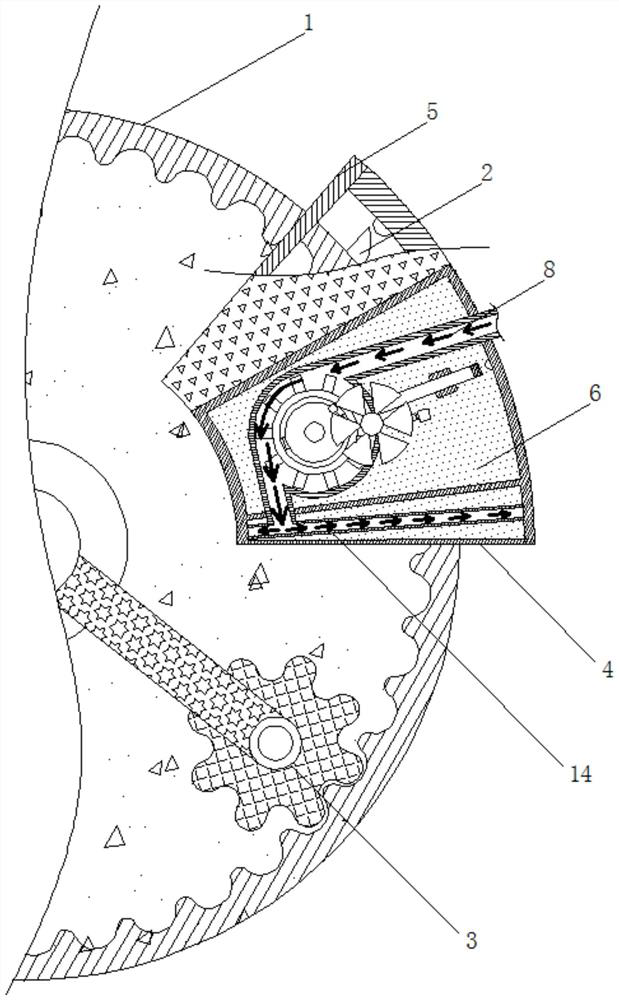
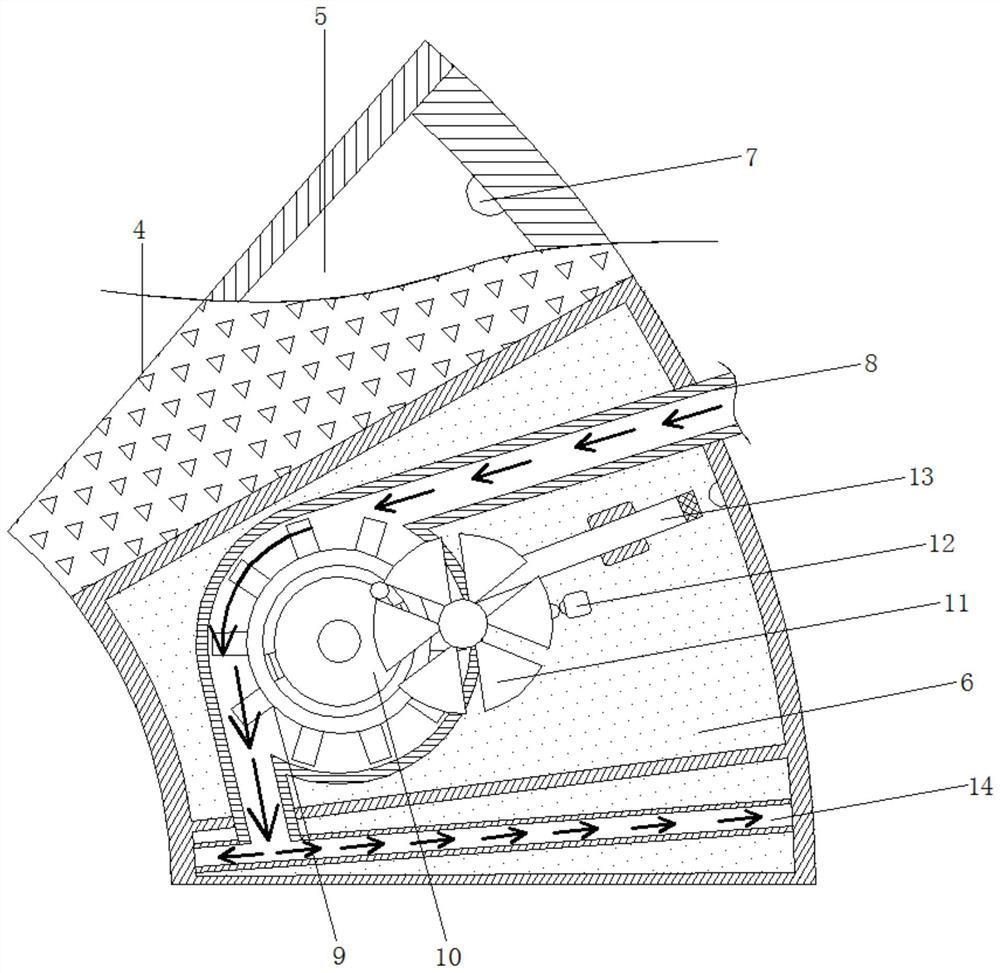
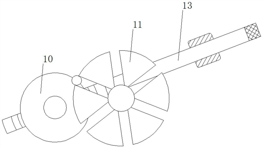
[0024] see Figure 1-4 , an automatic quenching and stopping device for surface quenching of metal molds, comprising a rotating tray 1, the surface of the rotating tray 1 is fixedly connected with a plectrum 2, the inner side of the rotating tray 1 is provided with a power wheel 3, and the right side of the rotating tray 1 A quenching device 4 is provided, the upper end of the quenching device 4 is provided with a fire spraying device 5, the lower side of the ...


PUM


Abstract

The invention relates to the technical field of metal surface machining, and discloses an automatic quenching and stopping device for surface quenching of a metal mold. The automatic quenching and stopping device comprises a rotating tray, a poking piece is fixedly connected to the surface of the rotating tray, a power wheel is arranged on the inner side of the rotating tray, a quenching device isarranged on the right side of the rotating tray, a fire spraying device is arranged at the upper end of the quenching device, a water spraying device is arranged on the lower side of the fire spraying device, and a touch button is arranged in the fire spraying device. According to the automatic quenching and stopping device for surface quenching of the metal mold, through cooperative use of the rotating tray, the poking piece, the power wheel, the quenching device, the fire spraying device, the water spraying device, a water spraying opening and the like, different positions of the metal surface can be in contact with the quenching device through automatic rotation, the water spraying device is arranged, thus the heated metal surface can be cooled in time, the quenching effect is improved, and the quenching device is automatically closed after quenching is completed.

Description

technical field [0001] The invention relates to the technical field of metal surface processing, in particular to an automatic quenching and stopping device for surface quenching of metal molds. Background technique [0002] Quenching is a commonly used method of processing metal surfaces and is often used to improve the properties of metals. However, in the existing quenching process, the metal is often manually moved to heat up the surface in contact with the quenching device to a critical temperature to achieve the effect of quenching. However, the speed of manually moving the metal is not uniform, and the quenching time of the metal surface is not the same everywhere. It may cause the heating time in a certain place to be too long, so that the core temperature of the metal is too high, thereby affecting the effect of quenching, and may even cause the metal to fuse and damage the metal due to too long heating time, and some quenching devices do not have a cooling device. ...

Claims


Application Information

Patent Timeline
Patent Type & Authority Applications(China)
IPC IPC(8): C21D1/667C21D9/00C21D11/00C21D1/08
CPCC21D1/667C21D9/0068C21D11/005C21D1/08
Inventor 鲁宇
Owner 鲁宇
Learn More