Cam conjugate induction hardening equipment

An induction hardening and cam technology, applied in quenching devices, furnaces, heat treatment equipment, etc., can solve the problems of high use cost, large surface quenching depth, overheating of the cam tip, and achieve low use and manufacturing costs, uniform induction hardening, Guaranteed uniformity

Inactive Publication Date: 2013-04-10
CHONGQING UNIV
View PDF4 Cites 1 Cited by
  • Summary
  • Abstract
  • Description
  • Claims
  • Application Information

AI Technical Summary

Problems solved by technology

[0003] In the prior art, the induction hardening of the cam (shaft) adopts ring-type and profiling inductors, and the ring-type quenching inductor is only suitable for smaller cams (shafts), such as automobile camshafts, and the hardened layer of the cam The uniformity is not ideal, resulting in excessive quenching depth on some surfaces. For example, the use of ring-shaped and profiling sensors can easily cause overheating at the tip of the cam, and the depth of the hardened layer is deep. Shallow, uneven depth of final cam hardening
At the same time, profiling sensors are cumbersome to manufacture, and different cams (shafts) require different profiling sensors, which lead to high cost and low work efficiency

Method used


Image

  • Cam conjugate induction hardening equipment
  • Cam conjugate induction hardening equipment
  • Cam conjugate induction hardening equipment

Examples


Embodiment Construction

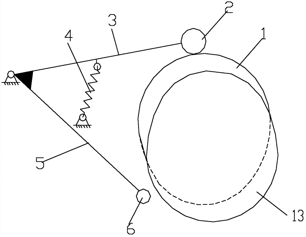
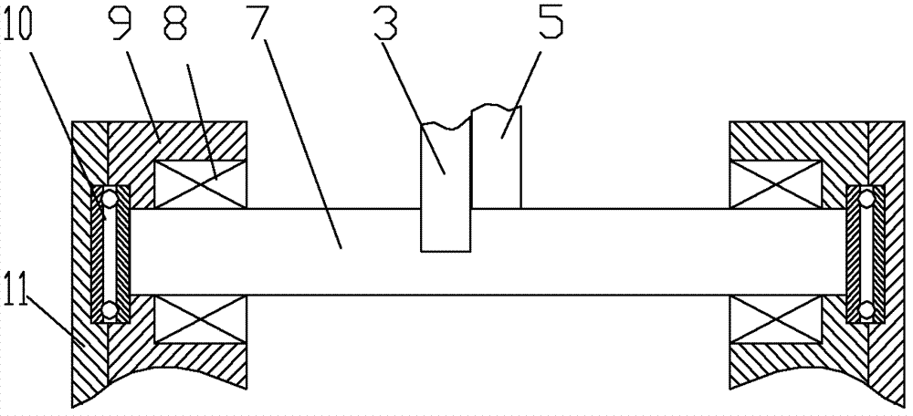
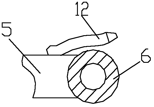
[0020] figure 1 Is a radial sectional view of the present invention, figure 2 Is an axial sectional view of the present invention, image 3 for figure 1 A view, as shown in the figure: the cam conjugate induction hardening device of this embodiment includes a driving rod 3, a follower rod 5, and a driving cam 1 that forms a conjugate cam group with the cam 13 to be quenched. The driving rod 3 It is fixedly connected to the follower lever 5 and hinged in a rotatable manner around a common axis. The end of the driving lever 3 away from the hinge point is provided with a roller 2 for contacting the working surface of the active cam 1, and the end of the follower lever 5 away from the hinge point The part is provided with an inductor 6 for induction hardening the working surface of the cam 13 to be quenched. The part on the working face of the cam 13 to be quenched is conjugated with the part where the active cam 1 is in contact with the roller. The drive rod 5 or The roller 2 is ...


PUM


Abstract

The invention discloses cam conjugate induction hardening equipment. The equipment comprises an active cam of a conjugate cam, and the active cam comprises a driving rod, a follower lever and a quenching required cam; the driving rod and the follower lever are fixedly connected and are hinged according to a way capable of rotating around a common axis; an end far from a hinge point of the drivingrod is provided with a roller contacting with a working face of the active cam; n end far from a hinge point of the follower lever is provided with a quenching inductor for induction quenching of a working face of the quenching required cam; a position right opposite to the working face of the quenching required cam is conjugated with a contact position of the active cam and the roller; and the driving rod or the roller is provided with pretightening force for pressing the roller on the working face of the active cam. According to the invention, a distance between the inductor and the quenching required cam is unchanged to guarantee that a linear velocity between the working face and the inductor is unchanged, so as to guarantee a same quenching time on each workpiece surface during a quenching process and endow each part of the working face of the quenching required cam with a basically same hardening layer depth.

Description

Technical field [0001] The invention relates to a heat treatment device for machine parts, in particular to an induction hardening device for cams. Background technique [0002] Cam is a more commonly used component in mechanical transmission. Since the cam transmission is carried out by sliding friction on the cam surface, the surface of the cam needs to be quenched during the cam manufacturing process to ensure hardness and wear resistance. [0003] In the prior art, cam (shaft) induction hardening uses ring-type and profiling inductors, and ring-type quenching inductors are only suitable for small-sized cams (shafts), such as automobile camshafts, and the hardened layer of the cam Unsatisfactory uniformity results in excessive hardening depth on some surfaces. For example, the use of ring-shaped and profiling inductors can easily cause overheating of the cam peach tip, deep hardening layer depth, difficult heating of the cam transition zone, and relatively deep hardening layer ...

Claims


Application Information

Patent Timeline
Patent Type & Authority Patents(China)
IPC IPC(8): C21D9/30C21D1/42C21D1/62
CPCY02P10/253Y02P10/25
Inventor 唐倩李忠华唐金涛金晓峰
Owner CHONGQING UNIV
Why Eureka
Try Eureka