Aspherical surface camera lens
A technology of photographic lens and aspheric surface, which is applied in the field of photographic lens, can solve the problems of enlargement, etc., and achieve the effect of ensuring telecentricity, good telecentricity, and suppressing telephoto ratio
- Summary
- Abstract
- Description
- Claims
- Application Information
AI Technical Summary
Problems solved by technology
Method used
Image
Examples
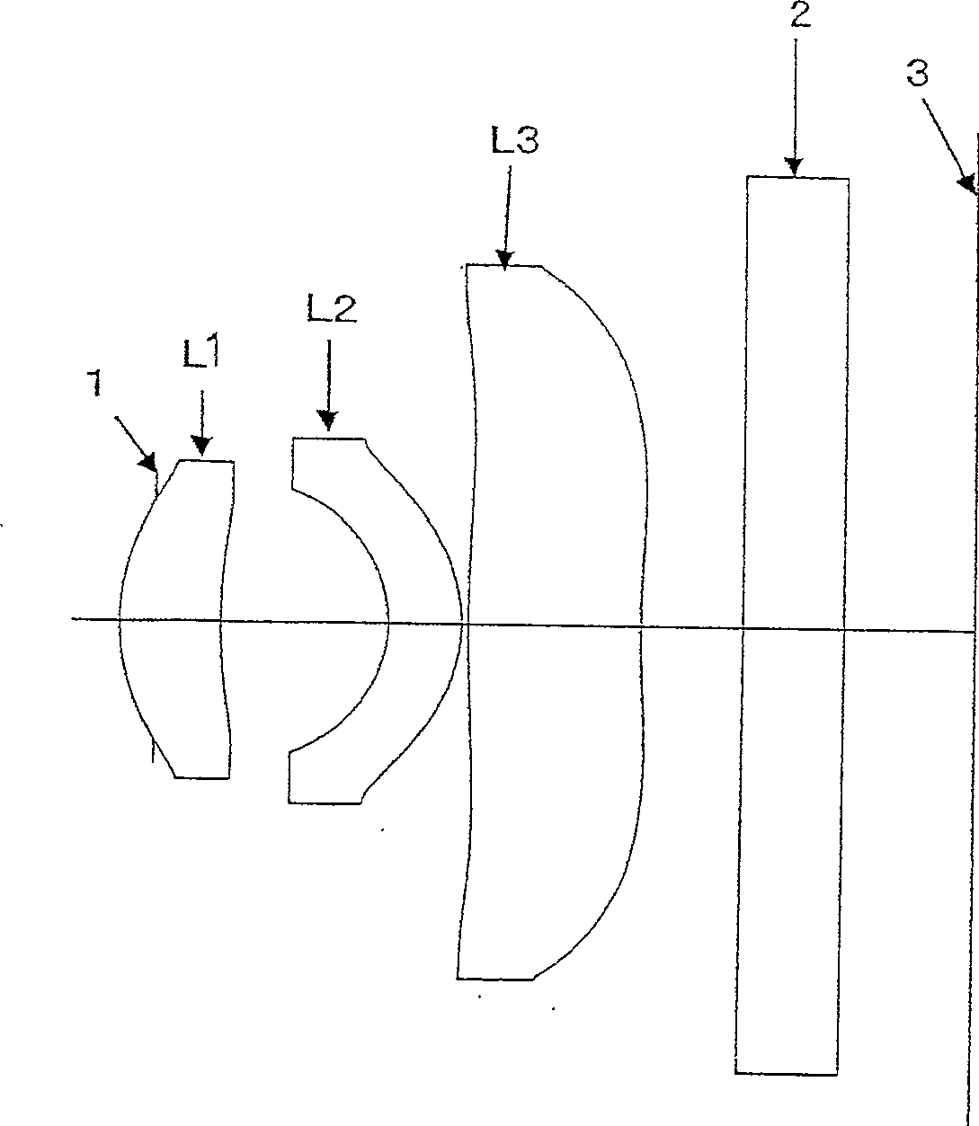
Embodiment 1
[0087] Focus distance: f=3.41
[0088] F NO: F2.89
[0089] Picture angle: 2ω=70.9°
[0090] r d n d v d
[0091] 1 1.086 0.48 1.54340 56.5
[0092] 2 2.822 0.78
[0093] 3 -0.649 0.35 1.58340 30.2
[0094] 4 -0.772 0.03
[0095] 5 5.950 0.84 1.51357 56.8
[0096] 6 4.879 0.50
[0097] 7 ∞ 0.50 1.51680 64.2
[0098] 8 ∞ 0.61
[0099] f / f 2 = 0.02
[0100] f / f 3 = -0.05
[0101] R 31 / R 32 = 1.22
[0102] d3 / d 1 = 1.75
[0103] T / f=1.15
[0104] α= 23.0° (Maximum incident angle of the camera element)
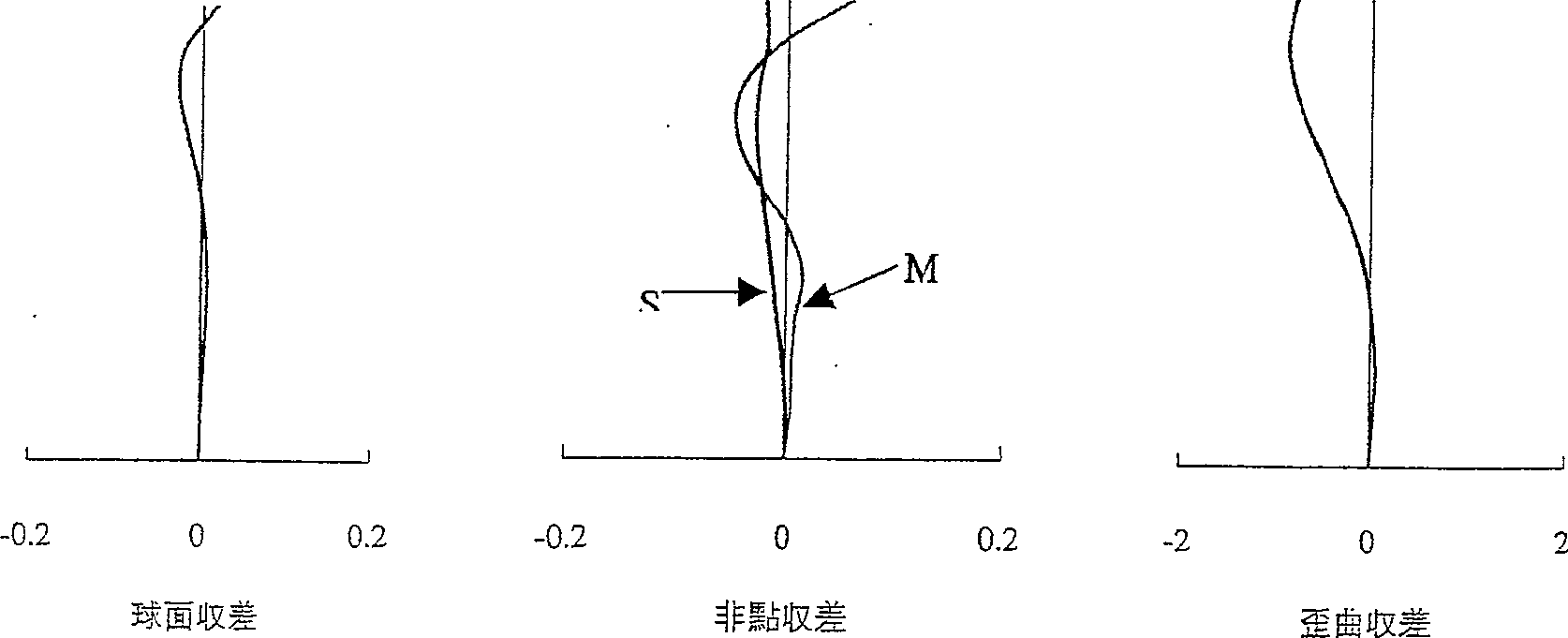
[0105] Spherical difference, abundant point difference, distorted difference
[0106] Pupil Height Area Height S M (Percentage)
[0107] 0 0 0 0 0 0
[0108] 0.1 0.001059 0.1 0.000538 0.005763 0.04163
[0109] 0.2 0.003674 0.2 -0.0022 0.00624 0.06538
[0110] 0.3 0.006384 0.3 -0.00816 0.009247 0.03118
[0111] 0.4 0.007321 0.4 -0.01312 0.015516 -0.03499
[0112] 0.5 0.004676 0.5 -0.01801 0.001716 -0.17472
[0113] 0.6 -0.00289 0.6 -0.02436 -0.02...
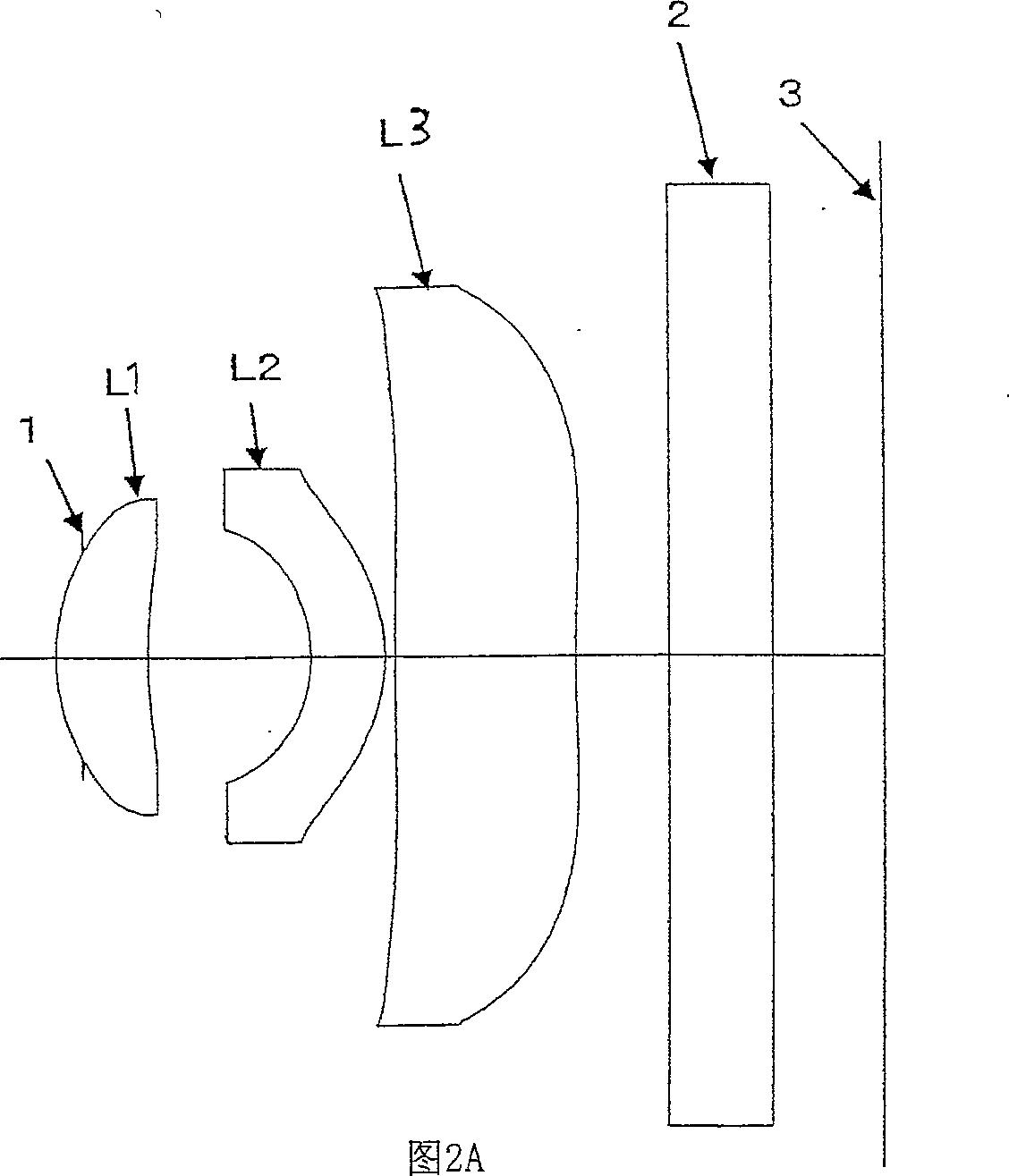
Embodiment 2
[0120] Focus distance: f=3.36
[0121] F NO: F3.43
[0122] Picture angle: 2ω=71.6°
[0123] r d n d v d
[0124] 1 1.016 0.43 1.54340 56.5
[0125] 2 2.812 0.75
[0126] 3 -0.740 0.35 1.58340 30.2
[0127] 4 -0.877 0.05
[0128] 5 16.389 0.87 1.51357 56.8
[0129] 6 6.116 0.45
[0130] 7 ∞ 0.50 1.51680 64.2
[0131] 8 ∞ 0.52
[0132] f / f 2 = -0.02
[0133] f / f 3 = -0.17
[0134] R 31 / R 32 = 2.68
[0135] d 3 / d 1 = 2.02
[0136] T / f=1.12
[0137] α = 24.5° (the maximum incident angle of the camera element)
[0138] Spherical spread Non-point spread Distorted spread
[0139] Pupil Height Area Height S M (Percentage)
[0140] 0 0 0 0 0 0
[0141] 0.1 -0.00022 0.1 0.003894 0.015687 0.10127
[0142] 0.2 -0.00084 0.2 0.007271 0.02889 0.22746
[0143] 0.3 -0.00181 0.3 0.004197 0.027334 0.24727
[0144] 0.4 -0.00308 0.4 -0.00255 0.021644 0.1946
[0145] 0.5 -0.00477 0.5 -0.01022 0.008804 0.10546
[0146] 0.6 -0.00706 0.6 -0.01737 -0.0123 -0.0063...
Embodiment 3
[0153] Focus distance: f=3.37
[0154] F NO: F3.20
[0155] Picture angle: 2ω=71.0°
[0156] r d n d v d
[0157] 1 1.025 0.46 1.54340 56.5
[0158] 2 2.931 0.74
[0159] 3 -0.742 0.35 1.58340 30.2
[0160] 4 -0.895 0.03
[0161] 5 11.820 0.89 1.51357 56.8
[0162] 6 5.301 0.28
[0163] 7 ∞ 0.50 1.51680 64.2
[0164] 8 ∞ 0.65
[0165] f / f 2 = -0.07
[0166] f / f 3 = -0.17
[0167] R 31 / R 32 = 2.23
[0168] d 3 / d 1 = 1.93
[0169] T / f=1.11
[0170] α = 24.5° (the maximum incident angle of the camera element)
[0171] Spherical spread Non-point spread Distorted spread
[0172]Pupil Height Area Height S M (Percentage)
[0173] 0 0 0 0 0 0
[0174] 0.1 0.0016 0.1 0.010185 0.030312 0.1898
[0175] 0.2 0.006118 0.2 0.019191 0.044109 0.31237
[0176] 0.3 0.01278 0.3 0.017312 0.039342 0.21015
[0177] 0.4 0.020421 0.4 0.011898 0.039287 0.05612
[0178] 0.5 0.027459 0.5 0.006455 0.031398 -0.07446
[0179] 0.6 0.03196 0.6 0.001093 0.007964 -0.18709 ...
PUM
 Abstract
Description
Claims
Application Information
 - R&D
- Intellectual Property
- Life Sciences
- Materials
- Tech Scout
- Unparalleled Data Quality
- Higher Quality Content
- 60% Fewer Hallucinations
Browse by: Latest US Patents, China's latest patents, Technical Efficacy Thesaurus, Application Domain, Technology Topic, Popular Technical Reports.
© 2025 PatSnap. All rights reserved.Legal|Privacy policy|Modern Slavery Act Transparency Statement|Sitemap|About US| Contact US: help@patsnap.com


