

Electronic image pickup system and electronic image pickup
A camera and electronic technology, which is applied to the parts of the TV system, the body of the camera, the TV, etc., can solve the problems of wrong selection and wrong setting of the operation mode, and it is difficult to confirm the operation mode of the liquid crystal monitor, so as to increase the use, Easy-to-see effects
- Summary
- Abstract
- Description
- Claims
- Application Information
AI Technical Summary
Problems solved by technology
Method used
Image

Examples
no. 1 example
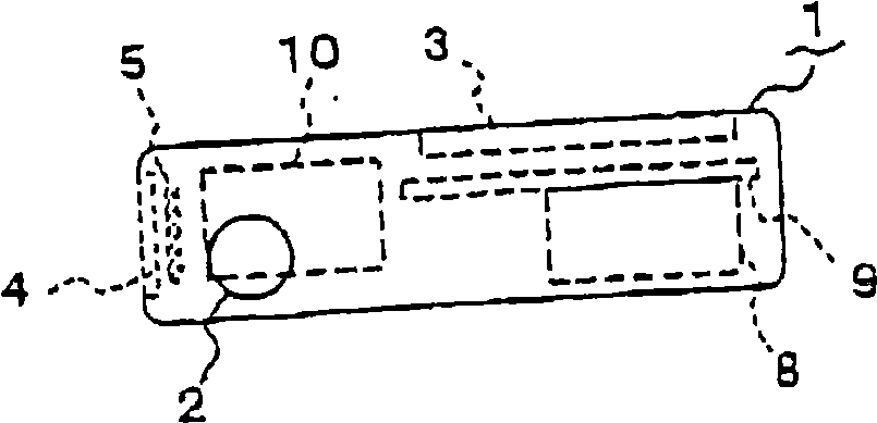
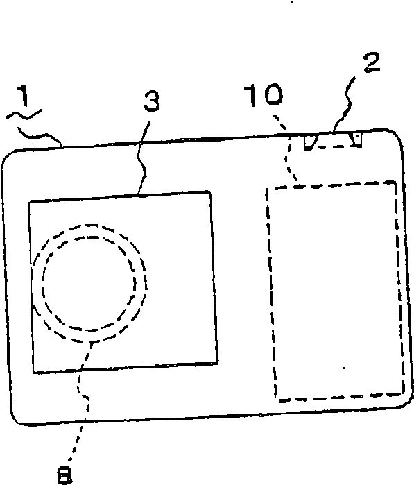
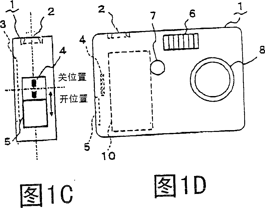
[0068] Such as Figure 1A ~Figure 1D, figure 2 , Figure 4A ~ Figure 4C , Figure 5 As shown, the electronic camera system according to the first embodiment of the present invention at least includes an electronic camera 1 and a camera bracket (hereinafter simply referred to as bracket) 18 on which the electronic camera 1 is mounted. The electronic camera 1 and the bracket 18 supply power from the bracket 18 to the electronic camera 1 through the connecting portion 4 and the connecting portion 20 having electrical contacts, and data is sent and received between the electronic camera 1 and the bracket 18 .
[0069] The above-mentioned electronic camera 1 selects and sets an appropriate operation mode according to the direction in which the electronic camera 1 is mounted on the holder 18, etc., and prohibits the setting of an inappropriate operation mode. That is, the electronic video camera 1 of this embodiment at least performs charging mode for charging a built-in secondar...
no. 2 example
[0134] Figure 8 is a main structural block diagram of an electronic camera system including the electronic camera 1 and the stand 18 according to the second embodiment of the present invention. To simplify the description, for and Image 6 The same components are represented by the same symbols, and descriptions are omitted.
[0135] Such as Figure 8 As shown, the electronic video camera 57 according to the present embodiment also has a lens cover (lens barrier) 58 and a lens cover switch (SW) 59 for protecting the taking lens section 30 and the like. The lens cover 58 of this embodiment is a manual cover that can be opened and closed by the user himself. The lens cover switch 59 is a switch for ON / OFF operation in conjunction with opening and closing of the above-mentioned lens cover 58 .
[0136] CPU64 execution and by Image 6 The processing performed by the CPU 41 shown is almost the same processing. Among them, the difference is that when selecting and setting an ...
no. 3 example
[0144] Figure 10 It is a front view showing a state in which the electronic camera according to the third embodiment of the present invention is loaded on the bracket with the front of the camera facing the front side of the bracket. Figure 11A with Figure 11B It shows that the electronic camera according to this embodiment is loaded relative to the bracket with the back of the camera facing the front side of the bracket, Figure 11A is the left side view, Figure 11B It is a front view. Figure 12 is a bottom view of the electronic video camera according to this embodiment. To simplify the description, the Figure 10 ~ Figure 12 , and the first embodiment ( Figure 1A ~ Figure 7 ) are denoted by the same reference numerals, and descriptions thereof are omitted.
[0145] This third embodiment is an example of a state in which the connecting portion 4 is provided on the bottom surface of the camera while the bracket is made to correspond thereto. Such as Figure 10 ,...
PUM
 Abstract
Description
Claims
Application Information