
Pulsation type heat pipe

A heat pipe and pulse tube technology, applied in the field of heat transfer elements, can solve the problems of low heat transfer, difficulty in starting, poor ability to overcome gravity, etc.

Inactive Publication Date: 2009-07-15
FU ZHUN PRECISION IND SHENZHEN +1
View PDF6 Cites 1 Cited by
  • Summary
  • Abstract
  • Description
  • Claims
  • Application Information

AI Technical Summary

Problems solved by technology

[0004] Existing pulsating heat pipes generally use capillary tubes with smaller diameters, and there is no additional capillary structure in the tubes, resulting in poor ability to overcome gravity, and it is difficult to start when the heat transfer is low

Method used


Image

  • Pulsation type heat pipe
  • Pulsation type heat pipe
  • Pulsation type heat pipe

Examples


Embodiment Construction

[0015] The present invention will be further described below in conjunction with the embodiments with reference to the accompanying drawings.

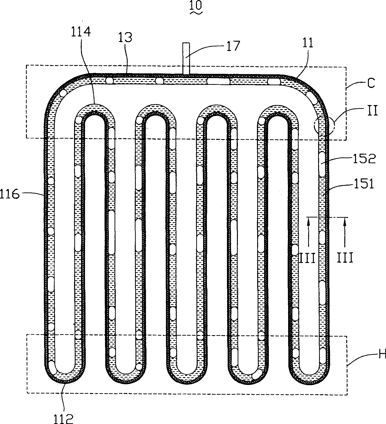
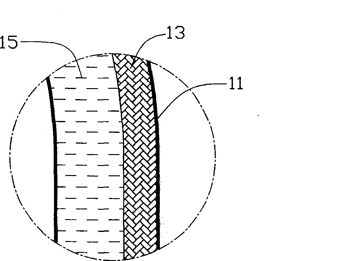
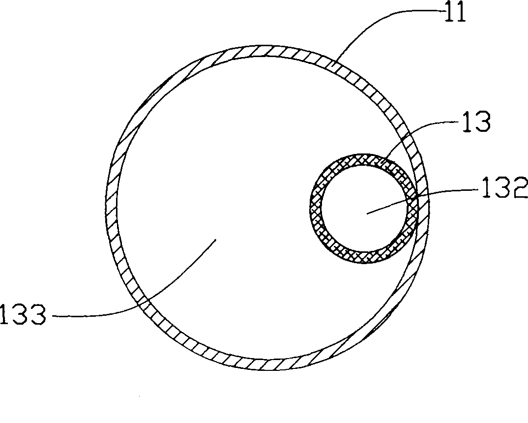
[0016] figure 1 Shown is a preferred embodiment of the pulsating heat pipe 10 of the present invention, the pulsating heat pipe 10 includes a continuously bent elongated capillary 11, a flexible braided vessel 13 and an appropriate amount of condensable working fluid 15 (such as figure 2 As shown), the vessel 13 is placed in the capillary 11, and the working fluid 15 is filled in the capillary 11 and the vessel 13. The capillary 11 is formed into a combination of multiple U-shaped tube bodies by continuous bending.

[0017] The capillary 11 is made of metal material, such as copper or aluminum. In this embodiment, the capillary 11 forms a closed loop (close loop) and its outline is generally palm-shaped, which has several U-shaped heat-absorbing sections 112, several U-shaped heat-dissipating sections 114, and The heat insulating s...


PUM


Abstract

This invention is pulse type heat tube. It includes capillary tube, working fluid in the capillary tube and vessel inside of the capillary tube. The said capillary tube is composed of several heat absorbing sections and several heat eliminating sections. There is hollow channel in the vessel. There is gap between the wall of vessel and capillary inner wall. The capillary force generated from the vessel can drive the working fluid flowing in the capillary tube, in order to increase the anti-gravity capacity of the pulse type heat tube. It makes the working fluid evenly distributed. This invention can be easily started in low heat transferring. It is adequate for temperature sensitive electronic elements.

Description

technical field [0001] The invention relates to a heat transfer element, in particular to a pulsating heat pipe. Background technique [0002] With the continuous improvement of the power of electronic components such as central processing unit (CPU), the problem of heat dissipation has been paid more and more attention by people. A pulsating heat pipe (PHP) is used as an effective heat transfer method in the field of heat dissipation due to its efficient heat conduction performance. [0003] At present, the pulsating heat pipe usually includes a continuous curved slender capillary, which is filled with a working fluid as a carrier for heat transfer. After the capillary is vacuum-packed, the working fluid in the capillary forms a liquid, vapor When one end of the pulsating heat pipe (usually called the heating section) is heated, the vapor-liquid plunger in it absorbs heat, evaporates and expands, flows to the other end of the pulsating heat pipe (usually called the cooling...

Claims


Application Information

Patent Timeline
Patent Type & Authority Patents(China)
IPC IPC(8): F28D15/02
CPCF28D15/0266
Inventor 张长生刘睿凯王肇浩白先声
Owner FU ZHUN PRECISION IND SHENZHEN
Learn More