Camera device and camera device connecting method

A camera device and connection method technology, applied in the direction of static cameras, image communications, color TV components, etc., can solve the problems of complex structure, multi-space, increased manufacturing costs, etc., to simplify the connection structure and reduce manufacturing costs , The effect that does not damage the electrical performance

Inactive Publication Date: 2009-07-15
RICOH KK
View PDF5 Cites 0 Cited by
  • Summary
  • Abstract
  • Description
  • Claims
  • Application Information

AI Technical Summary

Problems solved by technology

In addition, a movable printed circuit board that can move integrally with the imaging element is provided, and since the fixed printed circuit board and the movable printed circuit board are connected through a flexible printed circuit board, it is necessary to connect the flexible printed circuit board The interface connecting the printed circuit board to the fixed printed circuit board, and the interface connecting the flexible printed circuit board to the movable printed circuit board complicate the structure, increase the manufacturing cost and occupy a lot of space

Method used


Image

  • Camera device and camera device connecting method
  • Camera device and camera device connecting method
  • Camera device and camera device connecting method

Examples


Embodiment Construction

[0092] Hereinafter, a digital camera according to an embodiment of the present invention will be described in detail with reference to the accompanying drawings. In the following embodiments, although various limitations are made on the constituent elements, types, combinations, shapes, relative arrangements, etc., these are merely examples, and the present invention is not limited thereto.

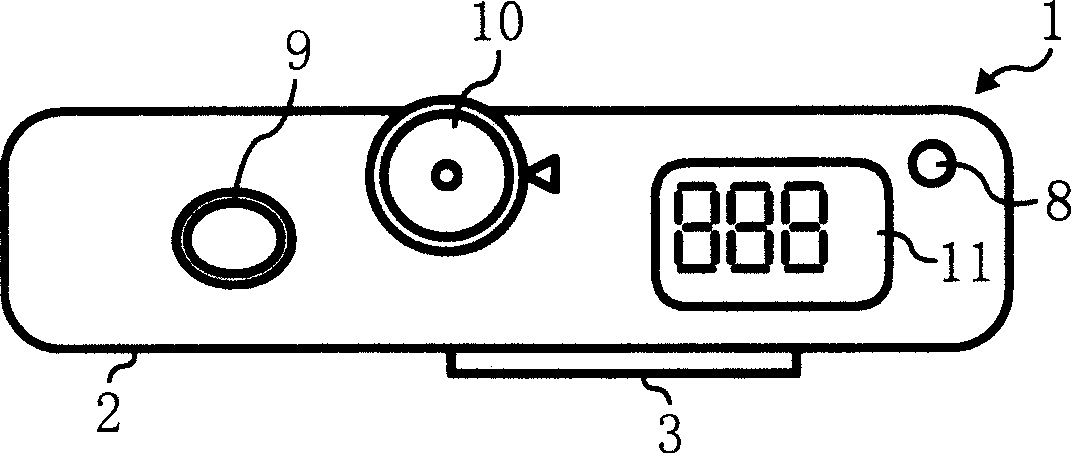
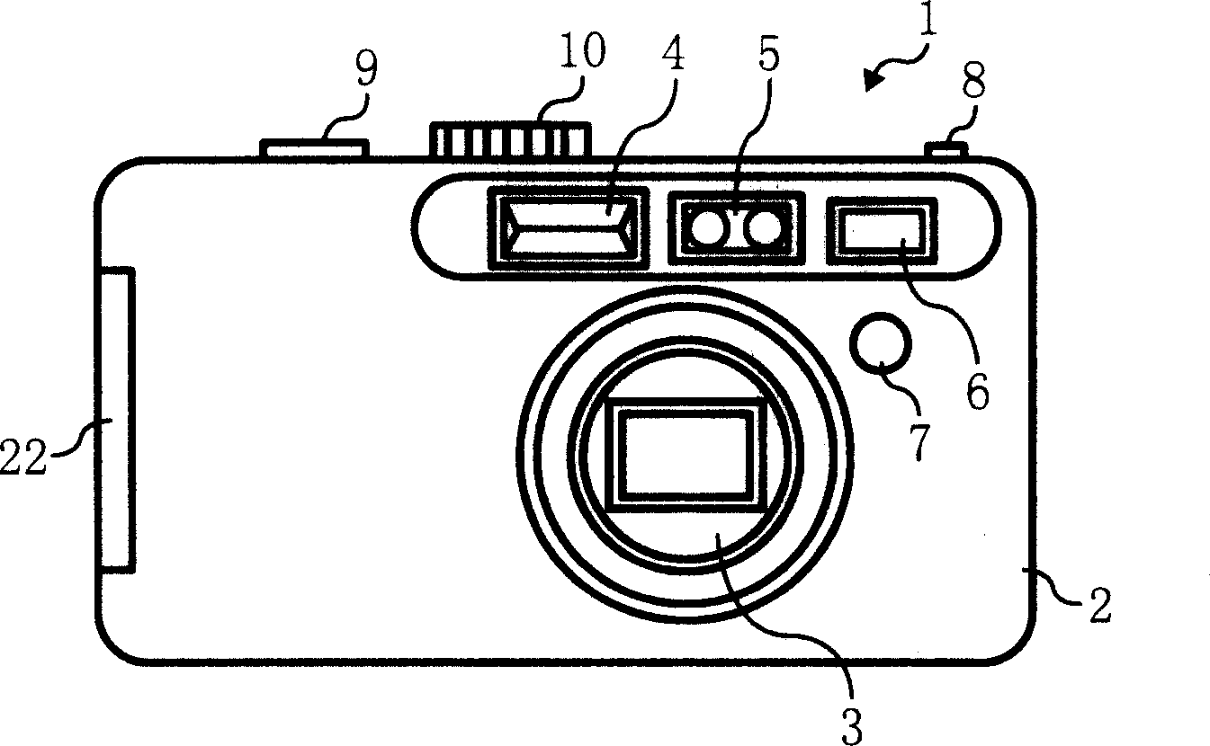
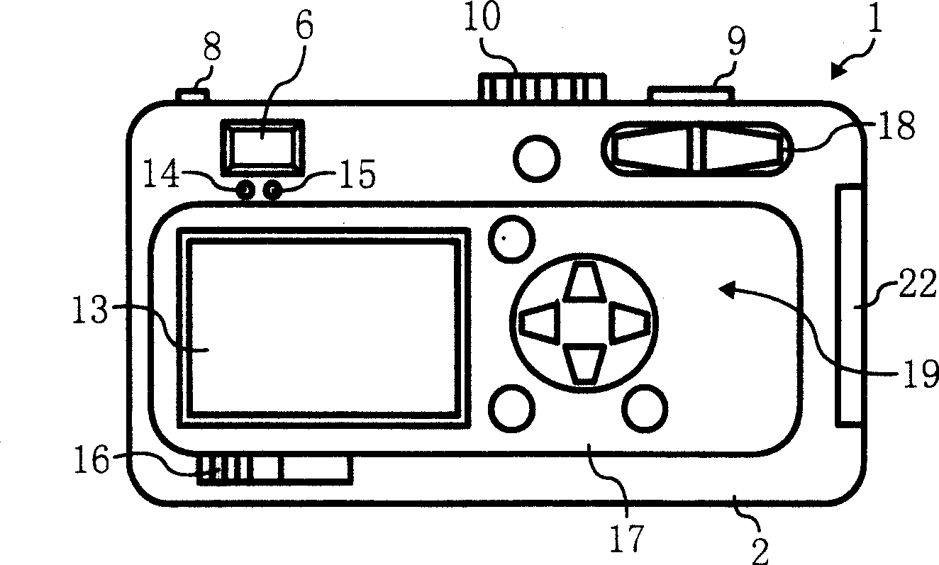
[0093] Figure 1-Figure 4Indicates the configuration of a digital camera. figure 1 A plan showing the overall composition of a digital camera, figure 2 Indicates looking from the subject's side figure 1 Front View Of Digital Camera. image 3 means looking from the photographer's side figure 1 and figure 2 rear view of a digital camera, Figure 4 express Figure 1-Figure 3 The block diagram of the digital camera system shown.

[0094] Figure 1-Figure 3 The illustrated digital camera 1 includes a camera body 2 including, on the front side with respect to the subject, a mirror un...


PUM


Abstract

The invention provides a connection method of an imaging apparatus for simplifying a connection configuration applied to a configuration for moving an imaging element for camera shake correction and attaining effective connection in an occupied space at a small manufacturing cost. A wiring pattern for delivering a CCD shift control signal and a wiring pattern for delivering a video signal are arranged on one and same flexible printed wiring board 121. A ground pattern PG for ground (GND) wires at a common ground level is arranged between a pattern region PS wherein the wiring pattern for the CCD shift control signal is arranged and a pattern region PI wherein the wiring pattern of the video signal is arranged. A mutual effect between the CCD shift control signal and the video signal of a CCD solid-state imaging element 45 is prevented by arranging the ground pattern PG between the pattern region PS wherein the wiring pattern for the CCD shift control signal is arranged and the pattern region PI wherein the wiring pattern of the video signal is arranged.

Description

technical field [0001] The present invention relates to an imaging device such as a digital camera, which obtains image information from an imaging element such as a solid-state imaging element, stores the image information in a recording medium, and has a correction function capable of correcting deviations caused by vibrations such as hand shake during shooting. More specifically, it relates to an imaging device, in which an optical image of a subject is formed by a photographic optical system, and vibration correction is performed by moving an imaging element such as a solid-state imaging element in the imaging optical system, and the present invention also relates to the connection of the imaging device. In the method, suitable electrical connections are made to an imaging element of the imaging device and a mechanism for moving the imaging element. Background technique [0002] In imaging devices such as still cameras and video cameras, when shooting still images, or wh...

Claims


Application Information

Patent Timeline
Patent Type & Authority Patents(China)
IPC IPC(8): H04N5/335H04N5/225H04N9/04H04N5/232H04N101/00
Inventor 吉田和弘
Owner RICOH KK
Why Eureka
Try Eureka