Supercharge Your Innovation With Domain-Expert AI Agents!

Sound image control system

A technology for controlling system and sound, applied in the direction of two-channel system, stereo system, quasi-stereo system, etc., can solve the problem of not being able to control the sound image of two listeners

Inactive Publication Date: 2009-07-22
PANASONIC CORP
View PDF3 Cites 0 Cited by
  • Summary
  • Abstract
  • Description
  • Claims
  • Application Information

AI Technical Summary

Problems solved by technology

Therefore, the above-mentioned sound image control system cannot simultaneously perform sound image control on two listeners.

Method used


Image

  • Sound image control system
  • Sound image control system
  • Sound image control system

Examples


no. 1 example

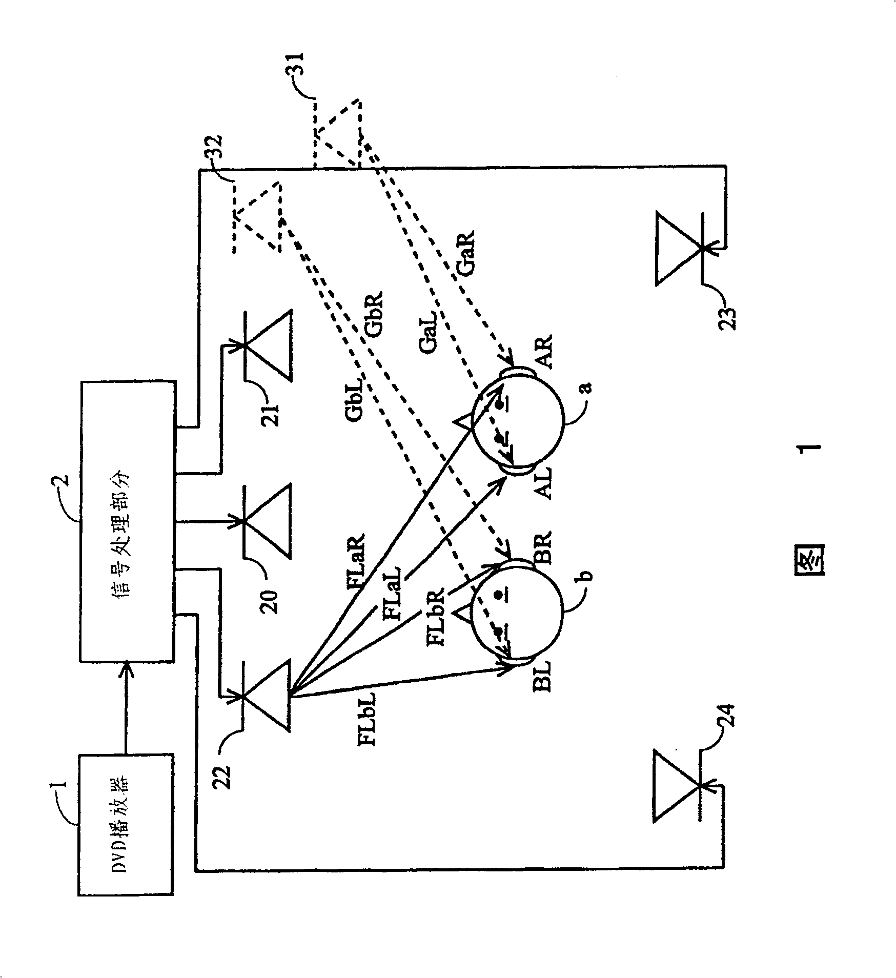
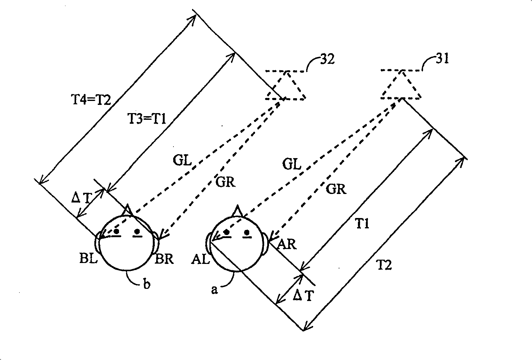
[0087] Fig. 1 is an illustration showing a sound image control system according to a first embodiment of the present invention. The sound image control system shown in Fig. 1 comprises: DVD player 1, is sound source; Signal processing part 2; CT loudspeaker 20, FR loudspeaker 21; FL loudspeaker 22; SR loudspeaker 23, SL loudspeaker 24; source 31; and target sound source 32 for listener b.

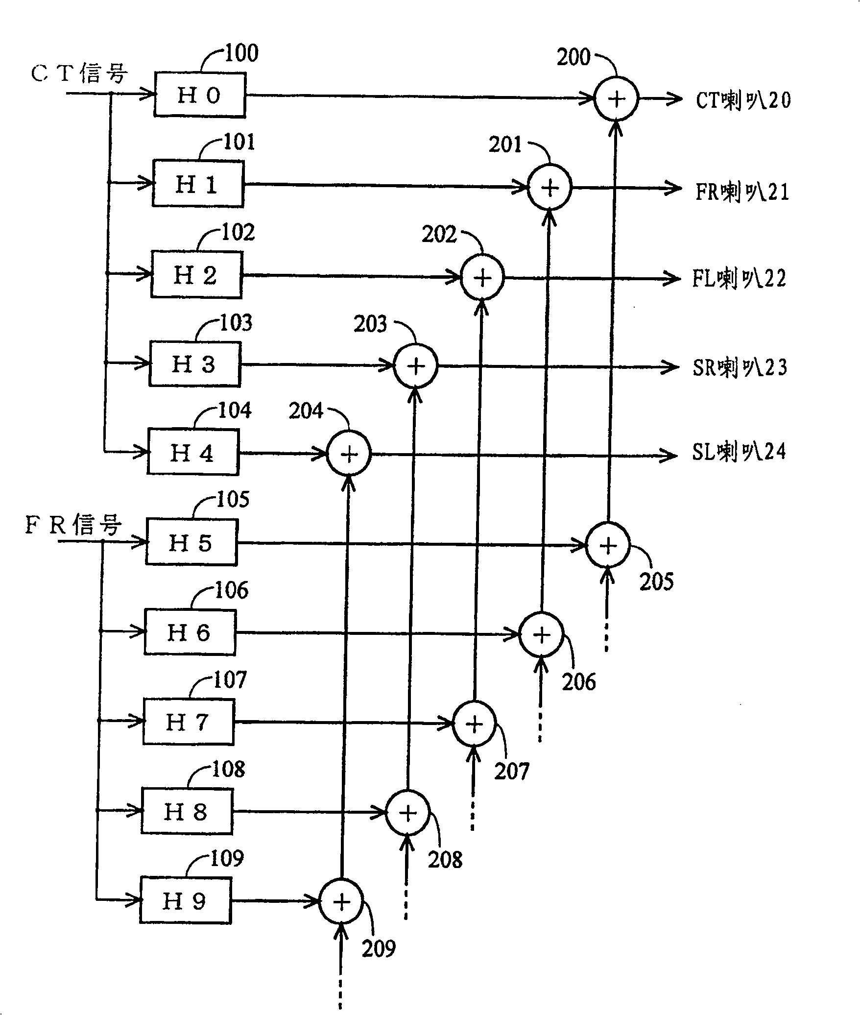
[0088] The DVD player 1 outputs, for example, 5-channel audio signals (CT signal, FR signal, FL signal, SR signal, and SL signal). The signal processing section 2 performs signal processing on the signal output from the DVD player 1, and the signal processing will be described below. The CT signal is signal-processed by the signal processing section 2 and input to 5 speakers. That is, during signal processing, five different filtering processes are performed on the CT signals, and the processed CT signals are input to the respective five loudspeakers. As in the case of the CT signal, the...

no. 2 example

[0136] In the following, a sound image control system according to the second embodiment is described. Fig. 16 is an illustration showing a sound image control system for performing sound image directional control on FR signals in the second embodiment. The structure of the sound image control system shown in FIG. 16 is different from the structure shown in FIG. 1 in that the SL speaker 24 is not used for sound image directional control of the FR signal. As was the case with the first embodiment, the goal of the second embodiment is to localize the sound image of the FR signal (and likewise for other channel signals) at the location of the target sound sources 31 and 32, but in the second embodiment the The number of loudspeakers is different from that used in the first embodiment. Specifically, in the first embodiment, 4 control points are controlled by 5 speakers 20 to 24 . On the other hand, in the second embodiment, four control points are controlled by four speakers 20 ...

no. 3 example

[0149] In the following, a sound image control system according to a third embodiment is described. Fig. 20 is an illustration showing the sound image control system according to the third embodiment. In Fig. 20, the above-mentioned sound image control system comprises: DVD player 1; Signal processing part 2; CT speaker 20; FR speaker 21; FL speaker 22; SR speaker 23, SL speaker 24: target sound source 31 of audience a ; target sound source 32 for listener b; display 500 ; and vehicle 501 . FIG. 20 shows the structure of the sound image control system ( FIG. 1 ) of the first embodiment, which is applied to a vehicle. As was the case with the first embodiment, the third embodiment aims at sound mapping the FR signal (and likewise for other channel signals) at the location of the target sound sources 31 and 32 . In FIG. 20, the speakers 21 and 22 are respectively placed on the two front doors (or in the area near the front doors). CT speaker 20 is placed near the middle of th...


PUM


Abstract

Provided is a sound image control system able to concurrently perform sound image localization control for two persons. The present invention is directed to a sound image control system controlling a sound image localization position by reproducing an audio signal from a plurality of loudspeakers. The sound image control system includes at least four loudspeakers for reproducing the audio signal and a signal processing section. The signal processing section sets four points corresponding to both ears of two listeners as control points, and performs signal processing for the audio signal input into the plurality of loudspeakers so that two target sound source positions indicating sound image localization positions of the respective two listeners are set in the same direction with respect to the two listeners. Here, the two target sound source positions are set so as to satisfy a following condition, T1 H04S 3 / 00 H04S 5 / 00 47 87 3 2003 / 6 / 9 1468029 2004 / 1 / 14 0000000 Matsushita Electric Industrial Co., Ltd. Japan Kakuhari Isao Terai Kenichi Hachuda Takahisa li jialin 31100 Shanghai Patent Agency Building 34--35, No.2650 Zhongshan North Road, Shanghai 200063 Japan 2002 / 6 / 7 2002-167197

Description

technical field [0001] The present invention relates to a sound image control system, in particular to a sound image control system for controlling the directional position of the sound image by playing back audio signals from a plurality of loudspeakers. Background technique [0002] In recent years, the multi-channel sound playback system represented by DVD has become popular. However, residential conditions often do not allow the installation of 5 or 6 loudspeakers. Therefore, a sound image control system using a so-called virtual playback method that realizes virtual playback of surround signals with left and right channel speakers has been developed. [0003] Also, especially in the sound image control system for car audio equipment, due to the considerable influence of reflection, reverberation, and standing waves, installation of speakers in a narrow space in the car is limited. In such a small space inside a car, it is often difficult to freely position the sound i...

Claims


Application Information

Patent Timeline
Patent Type & Authority Patents(China)
IPC IPC(8): H04S5/00H04S3/00H04S1/00
CPCH04S1/002H04R2499/13H04S3/008H04S3/00
Inventor 桥本裕之寺井贤一角张勋羽中田高尚
Owner PANASONIC CORP
Features
  • R&D
  • Intellectual Property
  • Life Sciences
  • Materials
  • Tech Scout
  • Unparalleled Data Quality
  • Higher Quality Content
  • 60% Fewer Hallucinations
Learn More