Power wire finishing device

A power cord and accommodating slot technology, applied in electrical digital data processing, instruments, digital data processing components, etc., can solve the problem of power cord being easily squeezed or broken

Inactive Publication Date: 2009-09-23
GIGA BYTE TECH CO LTD
View PDF3 Cites 0 Cited by
  • Summary
  • Abstract
  • Description
  • Claims
  • Application Information

AI Technical Summary

Problems solved by technology

[0004] The purpose of the present invention is to provide a power cord assembly device to solve the problem in the prior art that the power cord is easily squeezed or broken during the movement of the cooling fan, so as to protect the power cord and its plug connector from damage

Method used


Image

  • Power wire finishing device
  • Power wire finishing device
  • Power wire finishing device

Examples


Embodiment Construction

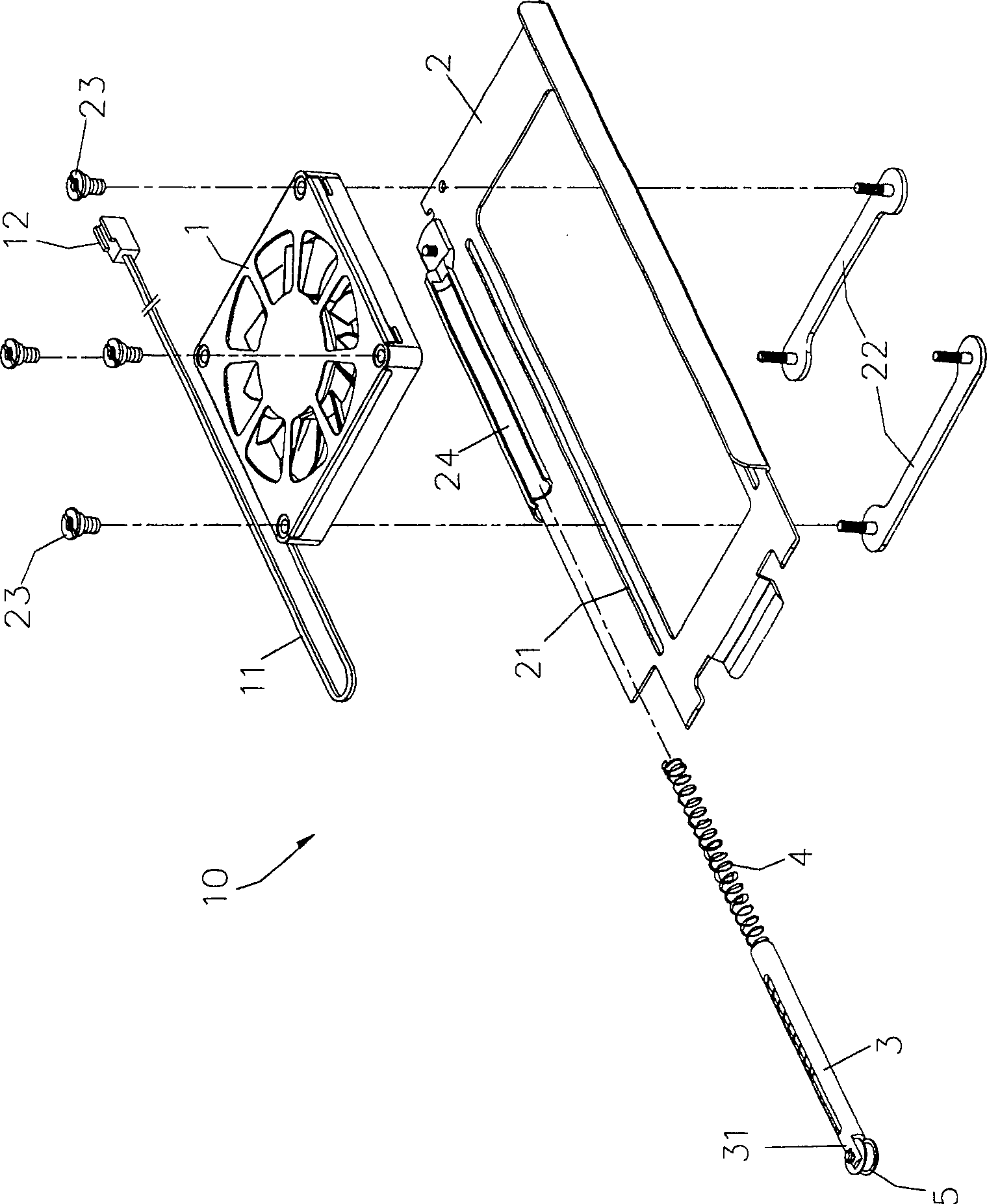
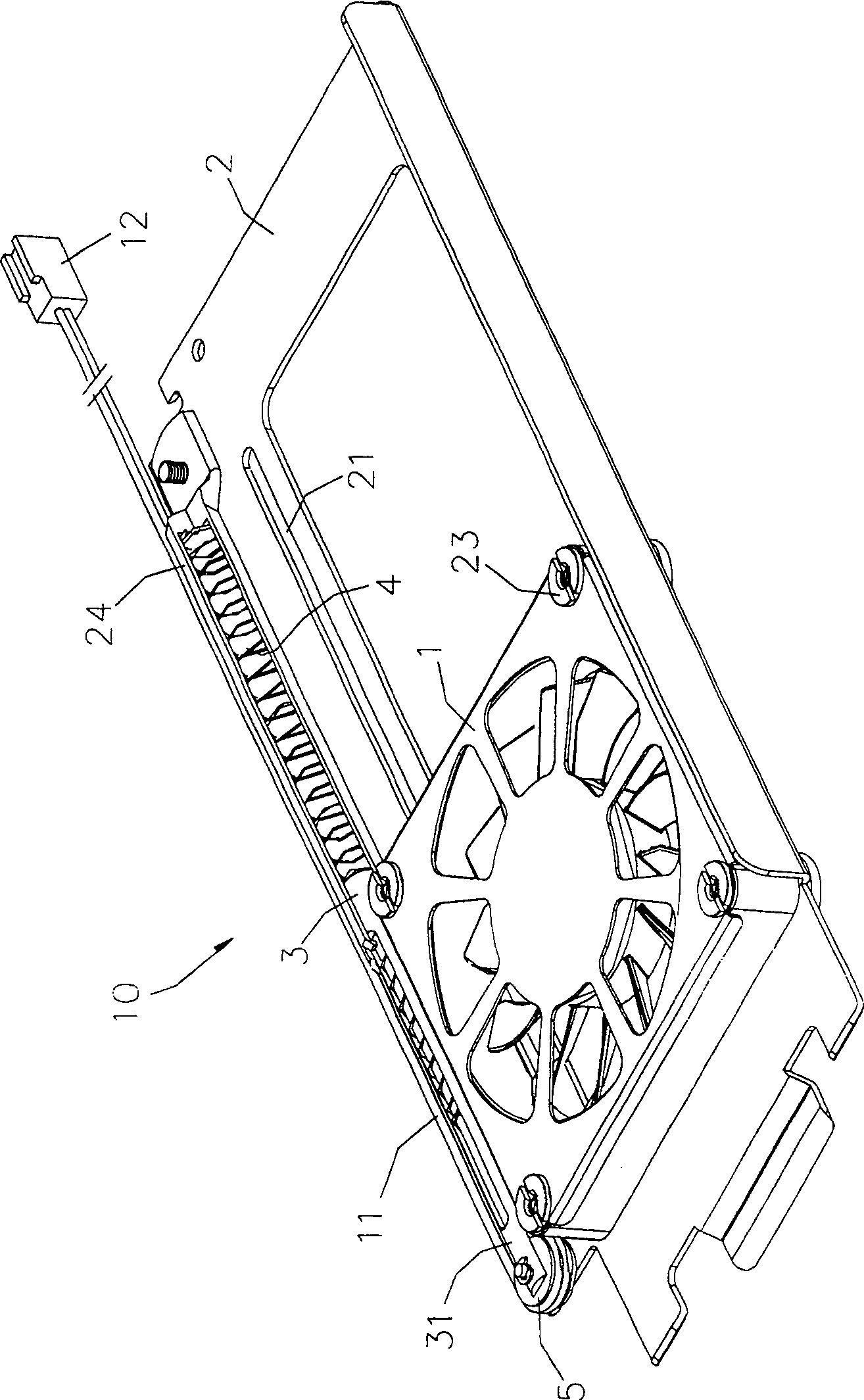
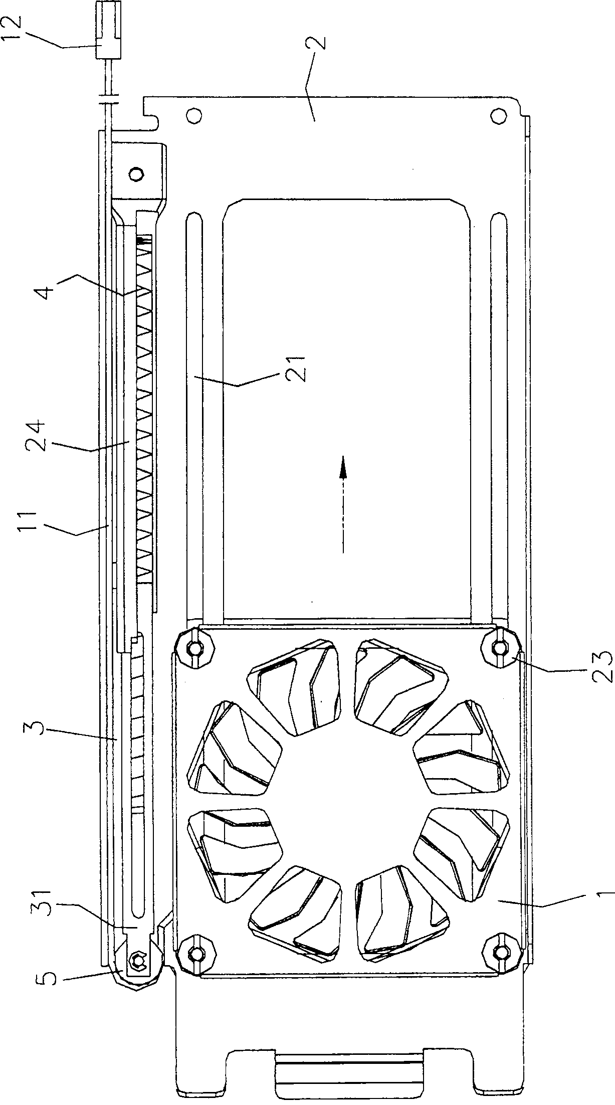
[0012] The present invention will be illustrated by preferred embodiments with reference to the accompanying drawings.

[0013] Such as figure 1 As shown, the wiring device 10 is applied to the cooling fan 1 of the cooling device. One end of the cooling fan 1 is extended and connected with a power cord 11 , and the other end of the power cord 11 is provided with a plug connector 12 . The line-integrating device 10 includes a base body 2 , which is in the shape of a long plate to carry the cooling fan 1 . A corresponding elongated hole 21 is provided on both sides of the base body 2 , and a fixing member 22 is sleeved from the bottom surface of the base body 2 to the elongated hole 21 , and the fixing member 22 can be adjusted and moved in the elongated hole 21 . After the cooling fan 1 is arranged on the base body 2, the cooling fan 1 is fixed on the base body 2 by locking the bolt element 23 and the fixing member 22, and adjusted and moved to a desired position on the base b...


PUM


Abstract

The invention relates to a power cord straightening device, which relates to a power cord straightening device for a radiator, which is used to solve the problem in the prior art that the power cord is squeezed or broken during the movement of the cooling fan. The whole line device of the power cord includes a base body, a positioning rod and an elastic element. The base body carries a heat dissipation fan, which can be adjusted and moved on the base body. One side of the base body is formed with an accommodating groove for setting one end of the positioning rod. The other end of the positioning rod is formed with an abutment portion; the two ends of the elastic element respectively abut against the corresponding end faces of the accommodating groove and the positioning rod; wherein the power line of the cooling fan is arranged on its side parallel to the axial direction of the positioning rod When the cooling fan is adjusted and moved on the base body, the positioning rod is pushed by the elastic element and follows the cooling fan for telescopic movement, and the power cord is pressed against the supporting part superior. Utilizing the power cord straightening device of the present invention, the power cord can be neatly straightened on the side of the positioning rod.

Description

technical field [0001] The invention relates to a power cord straightening device, in particular to a power cord straightening device applied to a heat dissipation fan of a heat dissipation device. Background technique [0002] Now most of the general computers are installed with various components or devices that will generate high temperature after operation, such as central processing unit, power supply, hard disk, etc., a cooling device must be used to assist heat dissipation to reduce the temperature inside the computer, so as to ensure its internal Each passive component or device can not be affected by high temperature. [0003] A general heat dissipation device mainly includes a base and a heat dissipation fan fixed on the base. In order to meet various heat dissipation requirements, the prior art provides a heat dissipation fan that can be adjusted and moved. However, during the movement of the cooling fan, the power cord connected to the cooling fan will inevitabl...

Claims


Application Information

Patent Timeline
Patent Type & Authority Patents(China)
IPC IPC(8): G06F1/20G06F1/16
Inventor 刘宜松刘贤沧
Owner GIGA BYTE TECH CO LTD
Why Eureka
Try Eureka