
Fixing device of head end of steel wire rope

A fixing device and wire rope technology, which is applied in medical science, X-ray equipment, electrical components, etc., can solve the problems of complex operation, high requirements for welding technology and pressing technology, and achieve the effect of simple operation, improved safety and assembly efficiency

Inactive Publication Date: 2010-12-08
SHENZHEN LANDWIND IND
View PDF6 Cites 0 Cited by
  • Summary
  • Abstract
  • Description
  • Claims
  • Application Information

AI Technical Summary

Problems solved by technology

[0004] The technical problem to be solved by the present invention is to provide a wire rope head-end fixing device, which overcomes the disadvantages of the prior art wire rope head-end fixing device that the operation is complicated when fixing the wire rope, and the requirements for welding technology and pressing technology are high

Method used


Image

  • Fixing device of head end of steel wire rope
  • Fixing device of head end of steel wire rope
  • Fixing device of head end of steel wire rope

Examples


Embodiment Construction

[0021] Hereinafter, the present invention will be further described in detail based on the drawings and embodiments:

[0022] Such as Figure 5 , Image 6 , Figure 7 with Figure 8 As shown, the wire rope head end fixing device of the present invention includes an adjusting rod 45. A threaded hole 451, a tapered hole 452 and a penetrating hole 453 are sequentially arranged along the axial direction of the adjusting rod 45, and also includes a tapered holding sleeve 43, At least one opening slot 431 is provided on the upper end of the tapered holding sleeve 43, the tapered holding sleeve 43 is placed in the tapered hole 452, and the locking bolt 41 is also included; when fixing the wire rope 46, pass the wire rope 46 through Hole 453 and tapered holding sleeve 43, and then screw the locking bolt 41 into the threaded hole 451.

[0023] The further optimization of the wire rope head end fixing device of the present invention is that it further includes a pressing block 42, which is ...


PUM


Abstract

The invention discloses a fixing device of the head end of a steel wire rope, which comprises an adjustment rod. A screwed hole, a tapered hole and a through hole which are mutually penetrated are sequentially arranged along the axial direction of the adjustment rod. The fixing device also comprises a tapered clasping sleeve, the upper end of the tapered clasping sleeve is provided with at least one open slot, and the tapered clasping sleeve is put in the tapered hole. The fixing device also comprises a lock nut. When the steel wire rope is fixed, the steel wire rope is penetrated through thethrough hole and the tapered clasping sleeve, and then the lock nut is screwed into the screwed hole. The fixing device of the head end of a steel wire rope can firmly fix the steel wire rope withouta physical damage to the steel wire rope by extruding the tapered clasping sleeve, and moreover, the operation for fixing the steel wire rope is quite simple, thus the safety and the assembly efficiency of a digital radiography system of a hanging frame structure are improved.

Description

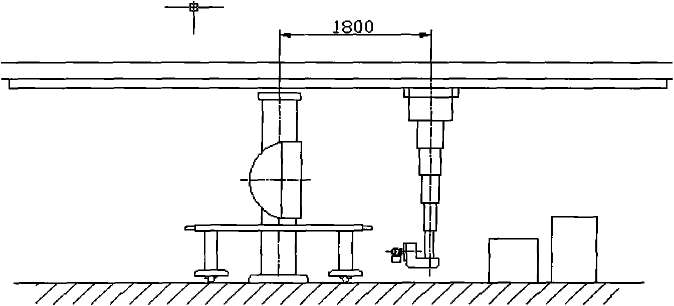
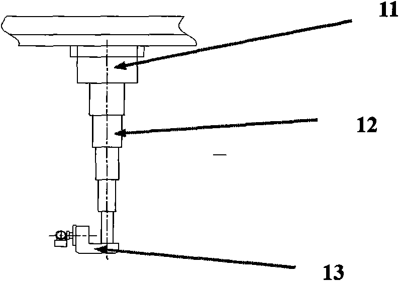
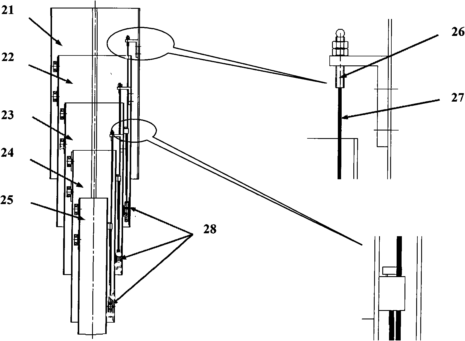
Technical field [0001] The invention relates to the technical field of medical equipment, in particular to a wire rope head end fixing device. Background technique [0002] figure 1 Shown is a digital radiography system with a suspension structure. figure 2 Shown is the telescopic crane of a digital radiography system with a suspension frame structure. The telescopic crane 12 has five cranes. The first crane is installed and fixed on the main frame 11, and the other four cranes pass through three wire ropes or chains. Connected together to achieve linkage, the nose 13 is installed at the bottom end of the last hoist in the telescopic hoist 12, and can be rotated along the vertical axis in a circle; the nose 13 is equipped with a bulb and light beam assembly , The component can rotate around the horizontal axis. [0003] Such as image 3 As shown, the five cranes of the telescopic crane 12 are connected by three wire ropes. One end of the first wire rope 27 is fixed to the crane 2...

Claims


Application Information

Patent Timeline
Patent Type & Authority Patents(China)
IPC IPC(8): F16M13/02F16M11/18A61B6/02H05G1/02
Inventor 王东平
Owner SHENZHEN LANDWIND IND
Learn More