
PCB version recognition device and method

A technology of identification device and identification method, which is applied in the direction of program control device, etc., can solve the problem that software or logic cannot achieve forward compatibility, and achieve the effect of ensuring forward compatibility

Active Publication Date: 2009-10-14
ZTE CORP
View PDF2 Cites 1 Cited by
  • Summary
  • Abstract
  • Description
  • Claims
  • Application Information

AI Technical Summary

Problems solved by technology

[0004] In order to solve the problem that the software or logic in the existing PCB version identification method cannot achieve forward compatibility, the present invention proposes a device and method for identifying the PCB version. The present invention can ensure the forward compatibility of the software and does not require only Upgrade logic version due to PCB version identification problem

Method used


Image

  • PCB version recognition device and method
  • PCB version recognition device and method
  • PCB version recognition device and method

Examples


Embodiment Construction

[0018] Embodiments of the present invention will be described in detail below in conjunction with the accompanying drawings.

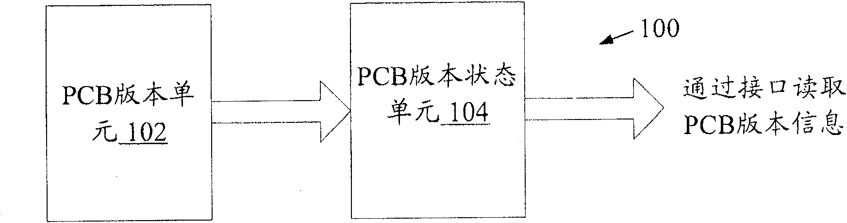
[0019] figure 1 A block diagram of a PCB version identification device according to an embodiment of the present invention is shown. refer to figure 1 , the PCB version identification device 100 according to an embodiment of the present invention includes: a PCB version unit 102 for marking PCB version information; and a PCB version status unit 104 for detecting and storing PCB version information.

[0020] The PCB version status unit 104 includes: an interface for allowing an external device to access the PCB version information stored in the PCB version status unit.

[0021] The PCB version unit 102 has logic independence.

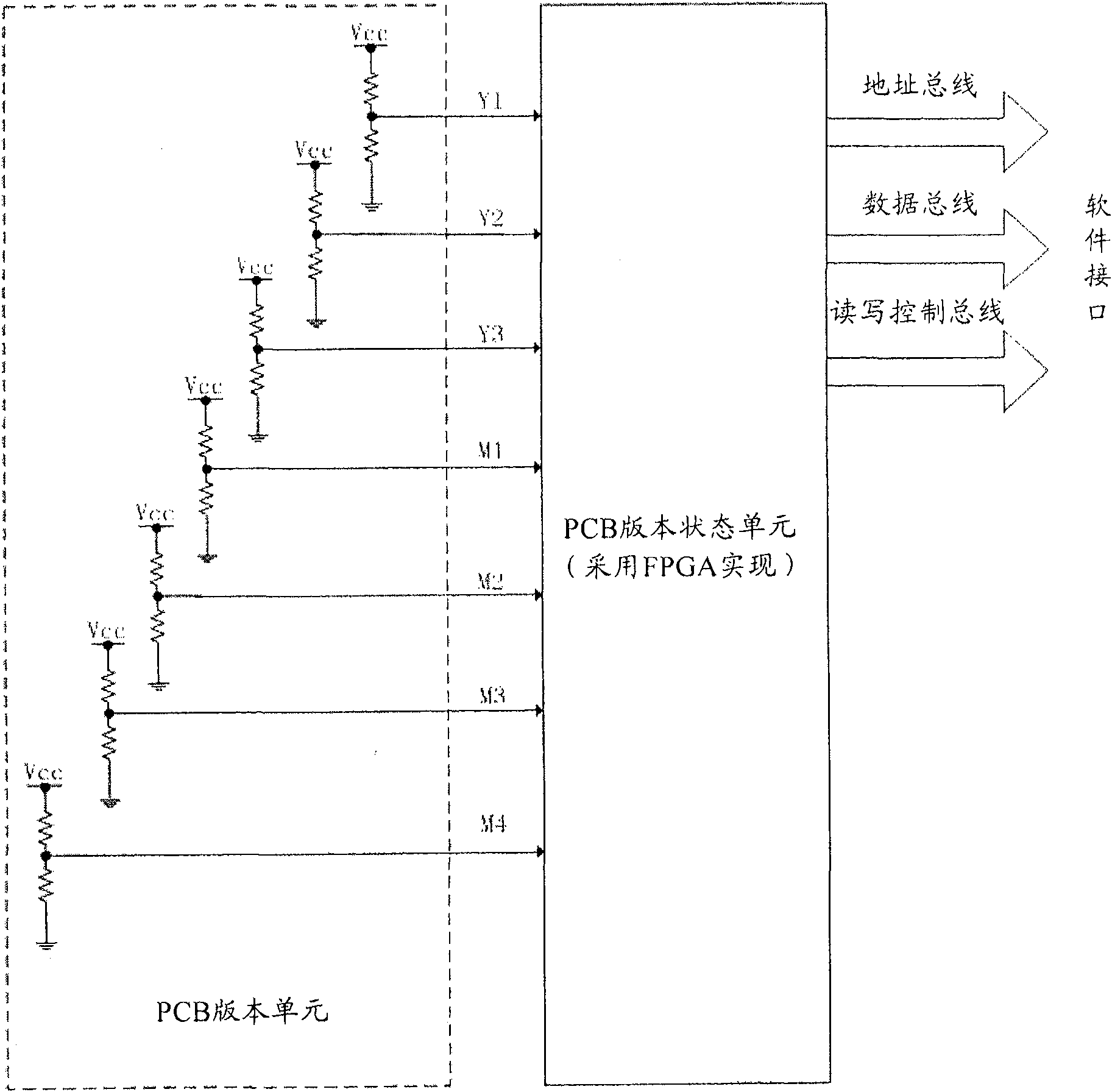
[0022] The PCB version unit 102 is composed of multiple sets of pull-up and pull-down resistors.

[0023] The PCB version status unit 104 is implemented by a field programmable gate array.

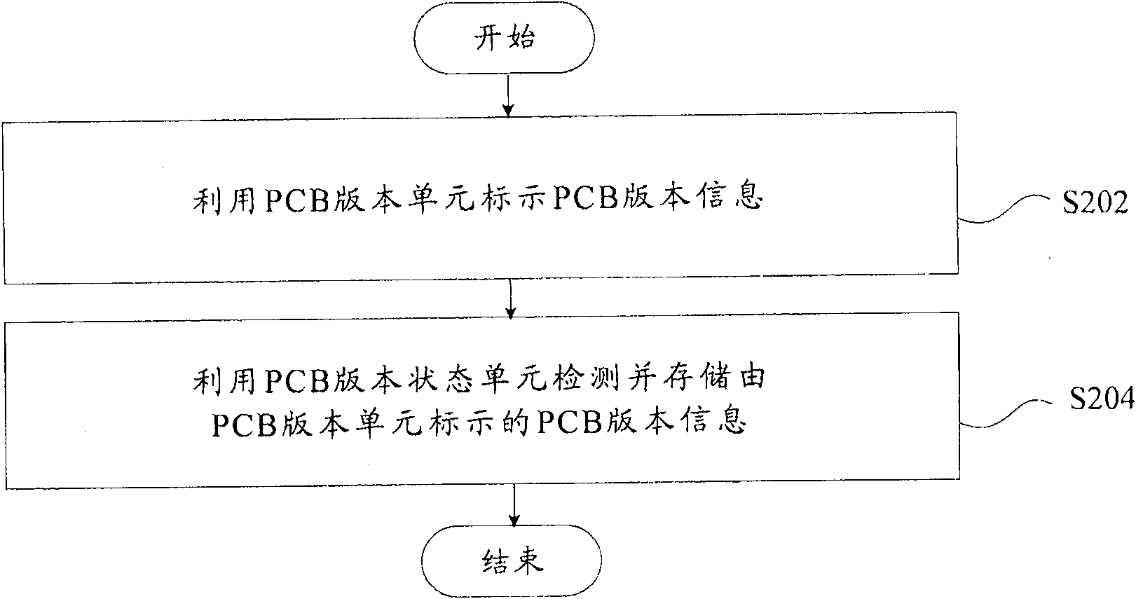
[0024] figure 2 A flow chart of...


PUM


Abstract

The invention discloses a PCB version identification device, comprising: a PCB version unit for marking PCB version information; and a PCB version state unit for detecting and storing the PCB version information. The invention also discloses a PCB version identification method. Adopting the present invention can not only ensure the forward compatibility after the software is upgraded, but also does not need to upgrade the logic version just because of the PCB version identification problem.

Description

technical field [0001] The invention relates to a communication equipment PCB version identification technology, in particular to a PCB version identification device and method. Background technique [0002] Modern society relies more and more on communication, and a large number of communication devices with different functions form the communication system of modern society. Communication equipment can be divided into terminal communication equipment and system communication equipment. Mobile phones, telephones, etc. belong to terminal communication equipment, and program-controlled switches, routers, etc. belong to system communication equipment. The system communication equipment is the core of the entire communication system. At present, the system communication equipment generally adopts the system structure of motherboard and plug-in board. The advantages of this system structure are flexible configuration and strong scalability. PCB (Printed Circuit Board) is an es...

Claims


Application Information

Patent Timeline
Patent Type & Authority Patents(China)
IPC IPC(8): G06F9/44
Inventor 尹景鹏
Owner ZTE CORP
Learn More