
Composite switch device

A compound switch and switch technology, applied in the direction of electric switches, emergency protection devices, electrical components, etc., can solve the problems of increasing the size of the switch body, reducing the contact state of movable contacts and fixed contacts, and increasing the movement of movable plates

Inactive Publication Date: 2009-10-14
U SHIN LTD
View PDF6 Cites 0 Cited by
  • Summary
  • Abstract
  • Description
  • Claims
  • Application Information

AI Technical Summary

Problems solved by technology

[0009] In particular, since multiple switches are accommodated in a compact switch body in a composite switch unit, the distance from the center of rotation of the operating lever to the engaging member that slides the movable plate is shortened. If you want to switch the switches reliably, then Since the distance between the movable contact and the fixed contact must be shortened, there is a problem of insulation. On the contrary, if the distance between the movable contact and the fixed contact has a margin, there is a difference between the movable contact and the fixed contact. The risk of reduced contact state between
[0010] In addition, these switches must switch multiple movable contacts and fixed contacts at the same time. However, if the operating angle of the operating lever is small, the movement amount of the movable plate is also small, so it is difficult to adjust the switching timing of each contact part. On the contrary, if the operating angle of the operating lever is increased, the operability is poor, and the moving amount of the movable plate also increases, so problems such as an increase in the size of the switch main body arise.

Method used


Image

  • Composite switch device
  • Composite switch device
  • Composite switch device

Examples


Embodiment Construction

[0046] The embodiments of the present invention will be described below based on the drawings.

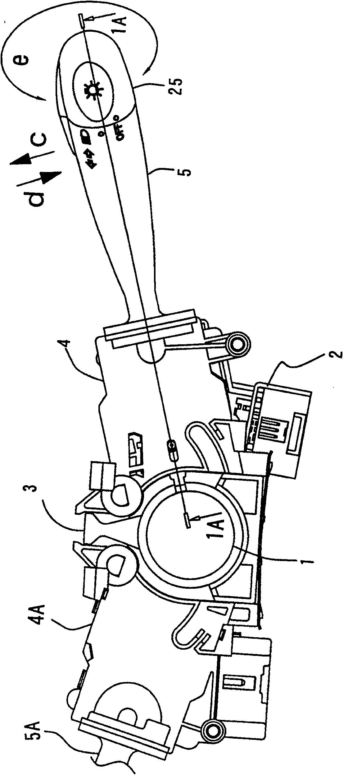
[0047] figure 1 It shows the steering shaft 1 and its surroundings on which a steering wheel (not shown in the figure) is installed to steer the car.

[0048] The peripheral portion of the steering shaft 1 is provided with an attachment portion 3 capable of attaching the composite switch device 2 from the side.

[0049] The mounting portion 3 is provided, for example, on a steering lock (not shown), and the composite switch device 2 is integrally mounted on the steering lock.

[0050] The composite switch device 2 is composed of a switch main body 4 and an operating lever 5, and the operating lever 5 can rotate along the up and down or back and forth directions of the switch main body 4.

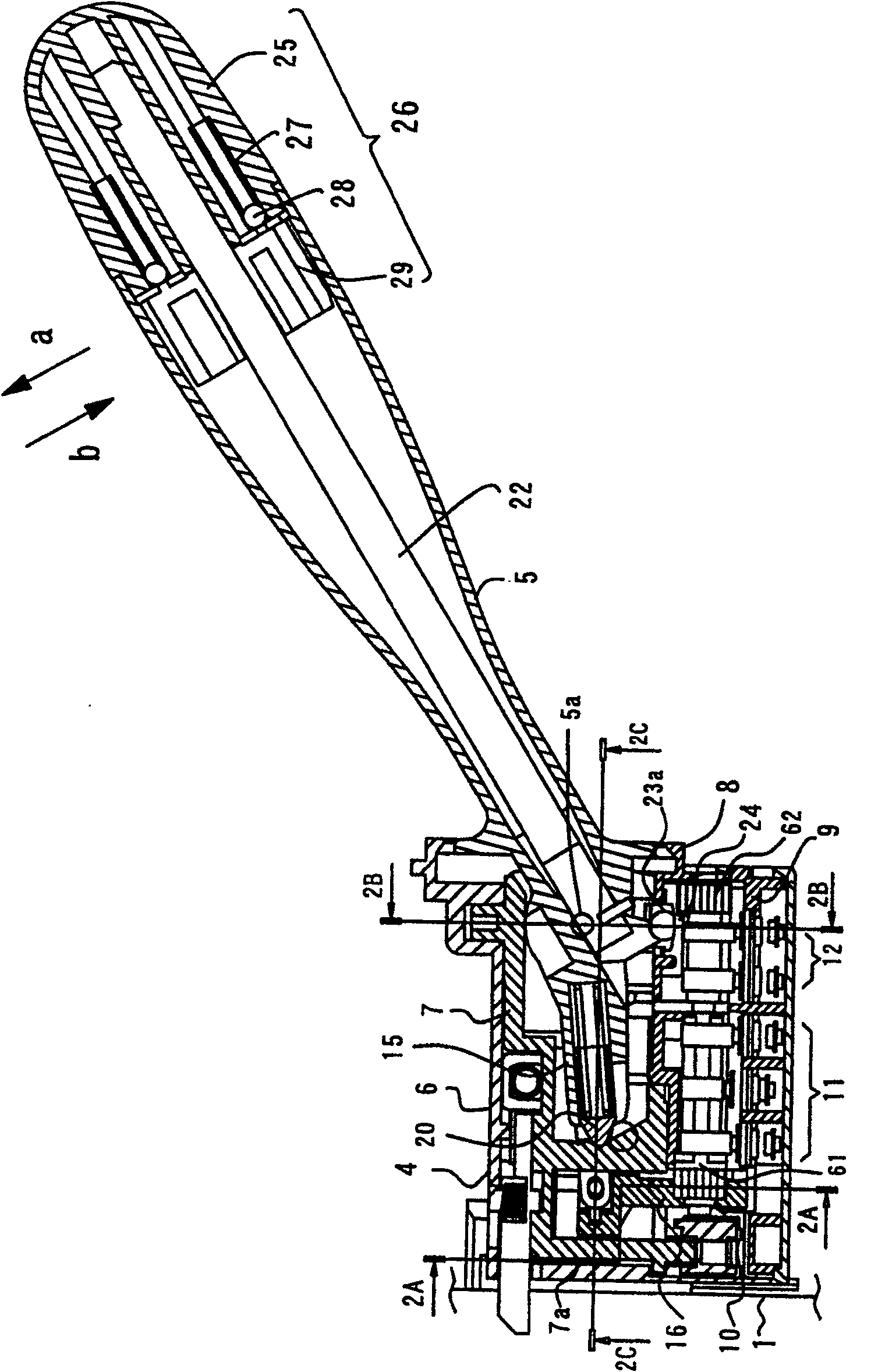
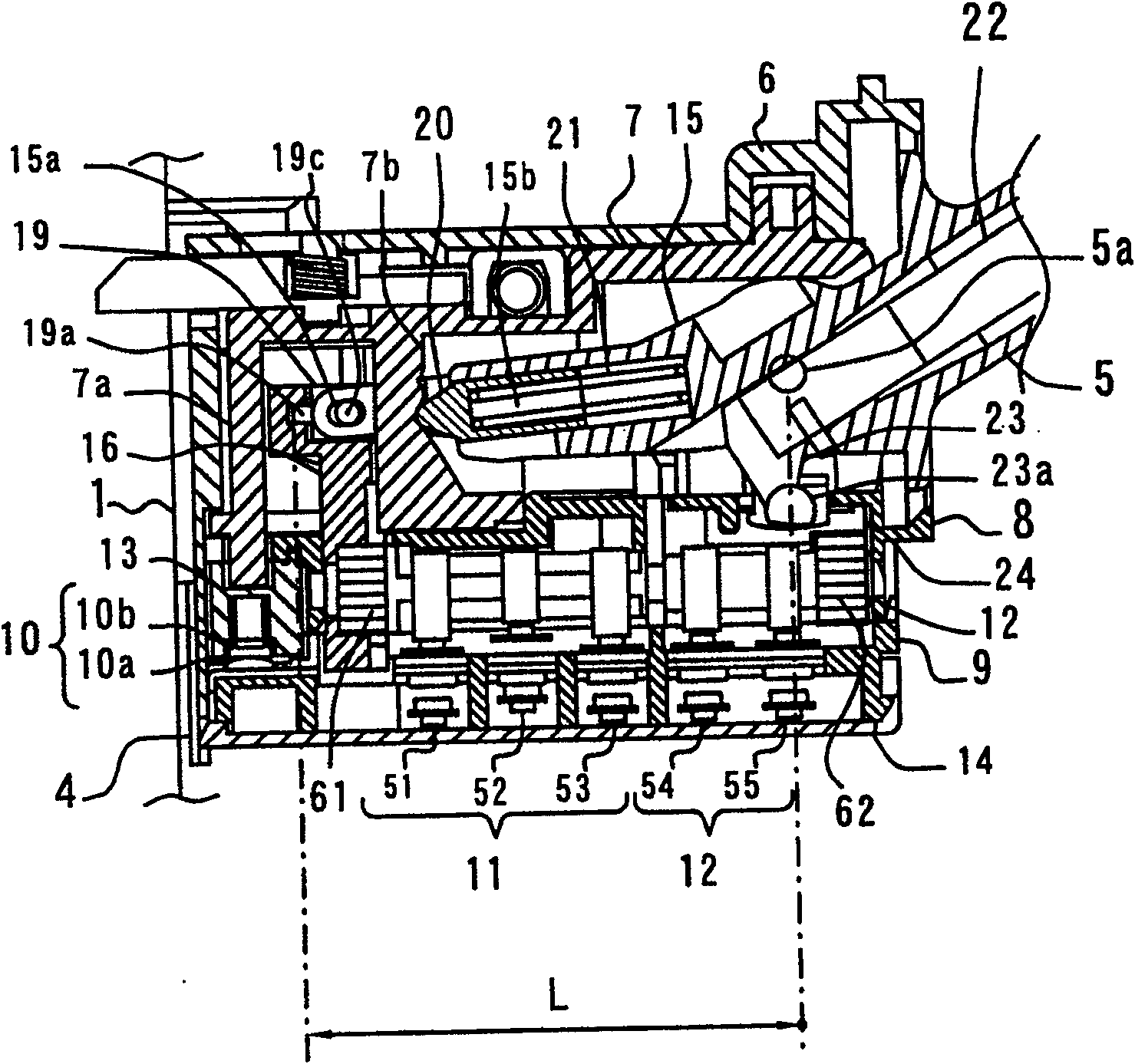
[0051] in figure 1 The inside of the switch main body 4 shown is like image 3 As shown, a switch 10, a dimmer switch 11, and a dimmer cam 12 are provided. Inside the switch main body 4A on the op...


PUM


Abstract

The present invention provides a composite switch device capable of switching a plurality of movable contacts and fixed contacts reliably. The composite switch device includes a switch main body and an operating rod. A plurality of switches with movable contacts and fixed contacts are assembled in the switch main body. The operating rod is arranged on the switch main body. To operate, the composite switch device includes a rod with a rack, which moves linearly with the action of one end of the operating rod; Moving linearly and rotating, the contacts of the above-mentioned switches are selectively operated by the above-mentioned cam, and even if the distance between the movable contact and the fixed contact has a margin, it can still be operated according to the less operation of the operating lever. Quantitatively realize the switching action.

Description

Technical field [0001] The present invention relates to a composite switch device that switches a plurality of switches such as a dimmer switch and a light switch of an automobile through the operation of an operating lever. Background technique [0002] The operating part that lights the direction indicator lamp or the headlamp of the automobile is generally arranged in a composite switch assembly, which is arranged on the periphery of the steering shaft where the steering wheel of the automobile is installed. [0003] The composite switch assembly is composed of an operating lever and an internal structure of a switch main body provided on the base end (supporting portion) side of the operating lever. [0004] Such a composite switch assembly is constructed in the following manner: a light switch that turns on the headlights and position lights, a dimmer switch that turns on the high beam or low beam to switch the direction of the headlight, Various switches such as turn signal...

Claims


Application Information

Patent Timeline
Patent Type & Authority Patents(China)
IPC IPC(8): H01H25/00H01H25/04H01H89/00
Inventor 森园和则
Owner U SHIN LTD
Learn More