Developing unit and image forming device
A developing device and image technology, applied in the direction of electric recording process applying charge pattern, equipment for applying electric recording process of charge pattern, electric recording technique, etc., can solve the problems of wrong operation, poor operability, etc. Good operability
- Summary
- Abstract
- Description
- Claims
- Application Information
AI Technical Summary
Problems solved by technology
Method used
Image
Examples
no. 1 example
[0051] (1) Color printer
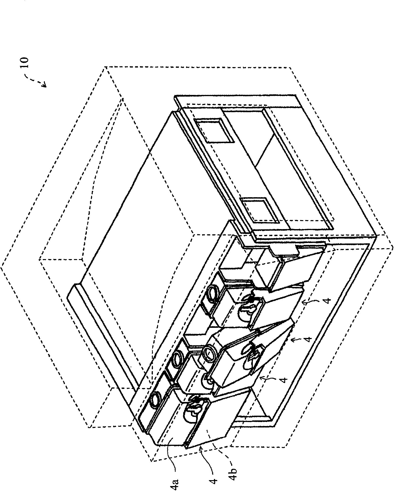
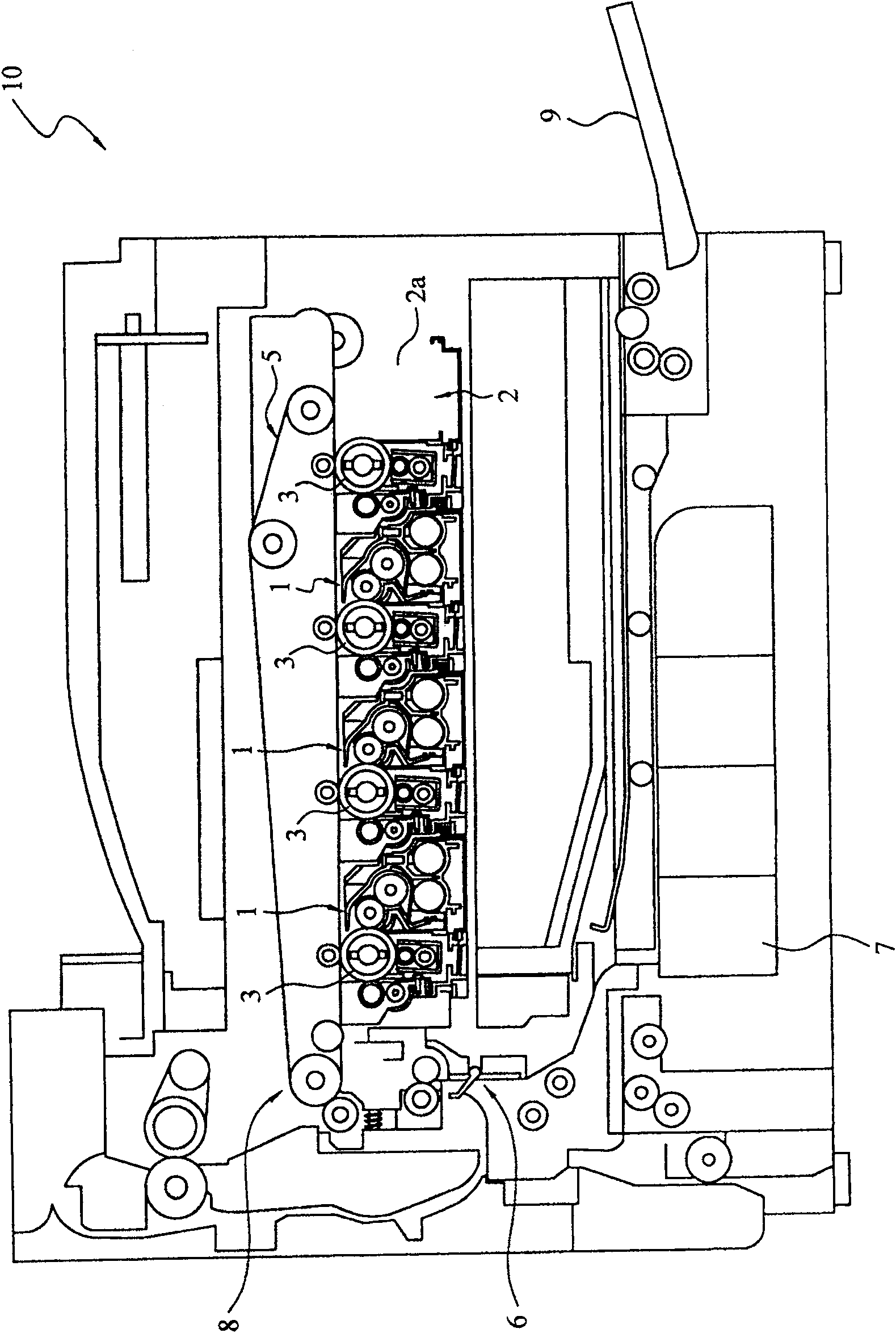
[0052] figure 1 and figure 2 A tandem type color printer 10 (image forming apparatus) employing the first embodiment of the present invention is shown. This printer 10 includes: a developing unit 1 (developing device); and a printer body (image forming apparatus body) on which the developing unit 1 is mounted. in addition, figure 2 Only three developing units 1 are shown, but a total of four developing units 1 can be mounted on the printer body.
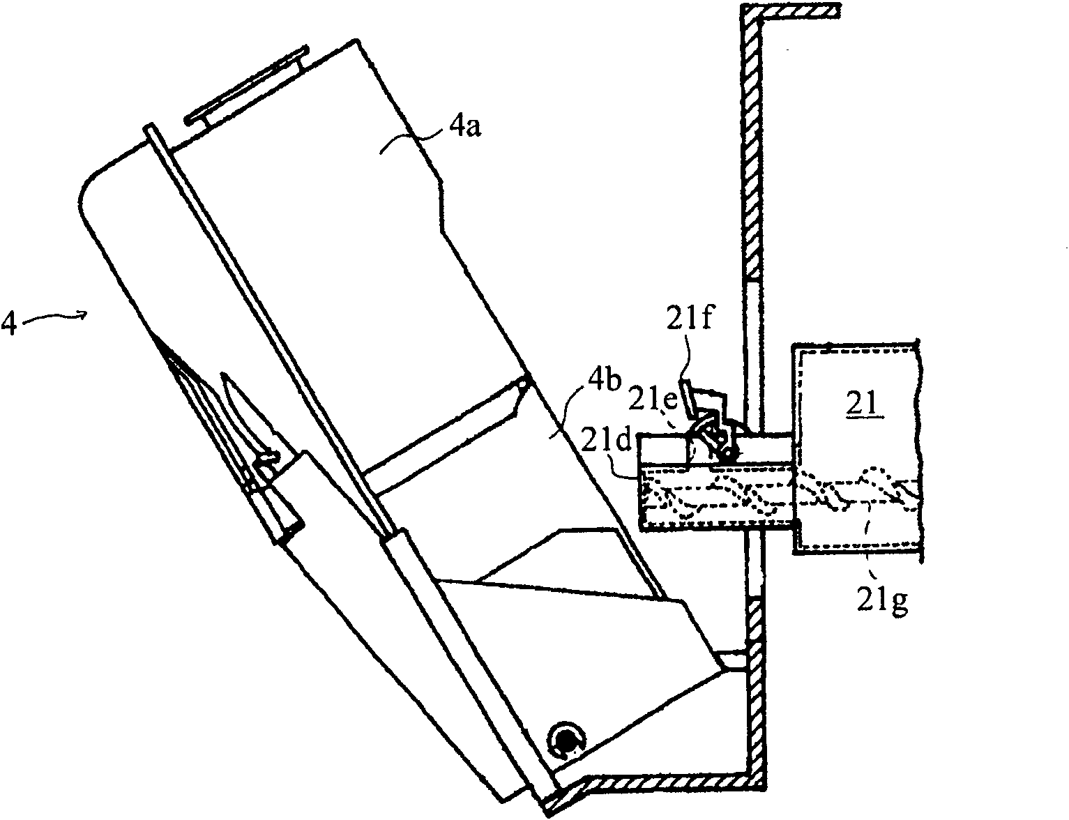
[0053] The printer body includes: four photosensitive drums 3 corresponding to four color toners of cyan, magenta, yellow and black respectively; four developing units 1; an intermediate transfer belt 5; four unit mounting parts 2; Toner storage unit 4 (opening and closing unit).
[0054] Each photosensitive drum 3 carries toner images of respective colors on the surface for transferring the toner images onto the intermediate transfer belt 5 .
[0055] The intermediate transfer belt 5 is an endless ...
no. 2 example
[0085] Here, description will focus on differences from the first embodiment.
[0086] Figure 8 A developing unit 101 mounted on a printer body employing the second embodiment of the present invention is shown. in addition, Figure 9 and Figure 10 Appearances of the arm member 123 and the bearing member 129 of the developing unit 101 are shown.
[0087] In the second embodiment, the front ends of the two arm members 123 are arranged below the shaft member 125 . In addition, each arm member 123 is biased to move its front end from the bottom to the top by a biasing mechanism (not shown) such as a spring in a free state. Its front end moves upward with the installation action, and with the detachment action, its front end is pushed downward against the urging force of the urging mechanism.
[0088] The shaft member 125 includes the two bent portions 125a and 125c similarly to the first embodiment, but here it is configured so that the two arm members 123 move upward simul...
no. 3 example
[0100] Here, the description will focus on the differences from the first and second embodiments.
[0101] Figure 13 It shows a state in the middle of the installation operation of the developing unit 201 according to the third embodiment. in addition, Figure 14 Shows the developing unit 201 in an installed state.
[0102] In addition, the printer body is basically the same as the first and second embodiments, but an escape hole 2b is formed on the abutted part 2a of the unit mounting part 2, and the end part inside the shaft member 225 of the developing unit 201 is further extended. Hold inward. Thus, as long as the developing unit 201 is pushed into the unit mounting portion 2 , the shaft member 225 will not move relative to the housing 221 .
[0103] The inner end portion 225b of the shaft member 225 of the developing unit 201 is not formed in a U-shape but in a shape extending in the axial direction. When the outer end portion 225d (second contact portion) is pushed ...
PUM
 Abstract
Description
Claims
Application Information
 - R&D Engineer
- R&D Manager
- IP Professional
- Industry Leading Data Capabilities
- Powerful AI technology
- Patent DNA Extraction
Browse by: Latest US Patents, China's latest patents, Technical Efficacy Thesaurus, Application Domain, Technology Topic, Popular Technical Reports.
© 2024 PatSnap. All rights reserved.Legal|Privacy policy|Modern Slavery Act Transparency Statement|Sitemap|About US| Contact US: help@patsnap.com


