Gas detection method and device

A gas detection and gas technology, applied in the field of low-cost infrared gas detection, can solve problems such as errors

Inactive Publication Date: 2009-11-18
IR MICROSYST
View PDF5 Cites 0 Cited by
  • Summary
  • Abstract
  • Description
  • Claims
  • Application Information

AI Technical Summary

Problems solved by technology

In the case of high gas concentrations, the accuracy of the measurement is limited by errors affecting the accuracy of the DC laser current of the modulated reference signal at frequency f

Method used


Image

  • Gas detection method and device
  • Gas detection method and device
  • Gas detection method and device

Examples


Embodiment Construction

[0025]In the following, the signal processing is described in detail as long as it differs from the prior art mentioned in WO 2005 / 026705 A1. The content of this document is incorporated by reference as far as signal processing is concerned, which signal processing may not be described in this specification.

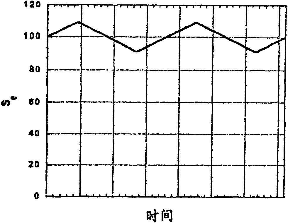
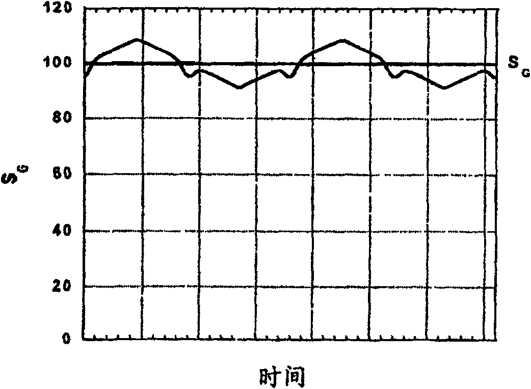
[0026] As already described and already mentioned in WO 2005 / 026705 A1, the laser source is operated with a DC current such that its wavelength corresponds exactly to the center of the gas absorption line. This current is constantly modulated with frequency f and amplitude such that the wavelength of the laser light completely scans the gas absorption line during each cycle by the corresponding AC modulation signal. figure 1 Shows as a function of time, reflected in the initial optical signal S 0 The laser output in which the detection region having the gas to be determined receives the laser output, and figure 2 shows the light intensity as a function of time, which ...


PUM


Abstract

The gas detector arrangement comprises at least one VCSEL source and at least one optical sensor for detecting a light beam which has passed through a sample chamber containing a given gas to be detected. The detection signal of the sensor is supplied directly to the electronic differentiator, or is time-derived by the electronic differentiator, and then supplied to the corresponding lock-in amplifier, so as to generate two different 2f-detections, f being the frequency of the wavelength modulation of the source, and Two corresponding measurement signals are thus provided which, when divided, give an exact value for the gas concentration. The present invention utilizes at least a first modulation reference signal and a second modulation reference signal each having a frequency twice the modulation frequency of the laser source. Providing at least a first 2f modulated reference signal is advantageous compared to the prior art because by using such a modulated reference signal one can measure the absolute intensity and thus receive the same result at different temperatures or mode hops of the laser. Another advantage is that the measurement accuracy is independent of gas concentration.

Description

technical field [0001] The present invention relates in particular to low cost infrared (IR) gas detection as disclosed in WO 2005 / 026705 A1. Background technique [0002] The gas detection method and gas detector device as described in this prior art publication are based on the formation of a vertical cavity surface emitting laser (VCSEL, Vertical Cavity Surface Emitting Laser) or distributed feedback (DFB, Distributed Feed Back) laser by wavelength modulation source, and the gas detection method and gas detector apparatus exploit the fact that the modulation of the wavelength is directly related to the modulation of the output intensity of the laser source. The intensity of light that has passed through the gas volume and is incident on the detector thus shows a first modulation related to the laser source intensity and a second modulation related to the gas absorption as the wavelength is scanned across the gas absorption line. Therefore, known detection methods and dev...

Claims


Application Information

Patent Timeline
Patent Type & Authority Patents(China)
IPC IPC(8): G01N21/35G01N21/39
CPCG01N21/3504G01J3/433G01N21/39G01N2201/0691
Inventor B·维林M·科利A·塞费尔特
Owner IR MICROSYST
Why Eureka
Try Eureka