Liquid crystal display, and driving method

A technology of liquid crystal display and driving method, which is applied in the field of color sequential liquid crystal display and its driving, and can solve problems such as drift and uneven brightness of liquid crystal display panels

Active Publication Date: 2009-11-18
AU OPTRONICS CORP
View PDF3 Cites 0 Cited by
  • Summary
  • Abstract
  • Description
  • Claims
  • Application Information

AI Technical Summary

Problems solved by technology

[0008] Therefore, the object of the present invention is to provide a liquid crystal display and its manufacturing method, to improve the phenomenon of uneven brightness of the liquid crystal display panel, and to improve the problem of gamma curve drift

Method used


Image

  • Liquid crystal display, and driving method
  • Liquid crystal display, and driving method
  • Liquid crystal display, and driving method

Examples


no. 1 example

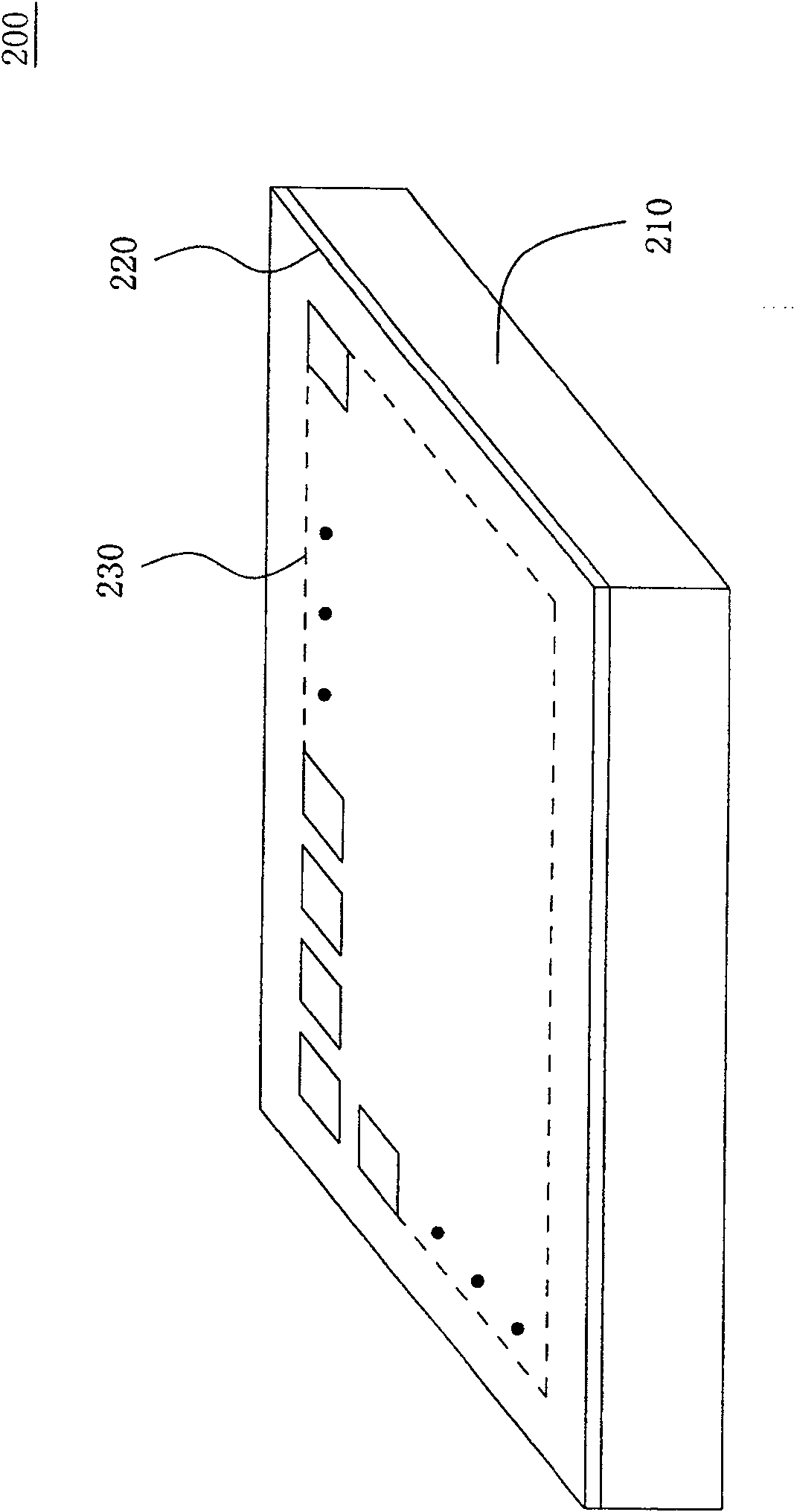
[0049] refer to figure 2 , is a schematic diagram of a liquid crystal display according to a first embodiment of the present invention. Also refer to image 3 , is a schematic diagram of the pixel array according to the first embodiment of the present invention. The liquid crystal display 200 includes a backlight module 210 and a liquid crystal display panel 220 having a pixel array 230 . The pixel array 230 includes a plurality of pixel columns L1 ˜ Ln, the pixels of which are respectively coupled to the scan driving circuit 240 through the scan lines 242 and coupled to the data driving circuit 250 through the data lines 252 . The scanning driving circuit 240 is used for providing the scanning voltage to the pixel, and the data driving circuit 250 is used for providing the pixel voltage to the corresponding pixel so as to change the light transmittance of the pixel.

[0050] refer to Figure 4, is a flow chart of the driving method of the liquid crystal display according...

no. 2 example

[0058] refer to Figure 7A , is a schematic diagram of a liquid crystal display according to a second embodiment of the present invention. Different from the first embodiment, in the liquid crystal display panel 700 , the display area of ​​the pixel array 710 is divided into a plurality of sub-display areas A1 -An. Each sub-display area includes a plurality of columns of pixels, and these pixels are respectively coupled to the scan driving circuit 720 and the data driving circuit 730 . In addition, one end of the storage capacitors of multiple columns of pixels in the first sub-display area A1 is coupled to the first common electrode line CL1, (the label of the line belongs to the label of the line, and the code of the signal belongs to the code of the signal) The second sub-display area A2 One end of the storage capacitors of multiple columns of pixels is coupled to the second common electrode line CL2, and so on, one end of storage capacitors of multiple columns of pixels i...


PUM


Abstract

The invention discloses a method for driving a liquid crystal display. First output the first pixel voltage to the first pixel in the first pixel column to change the light transmittance of the first pixel, and then output the second pixel voltage to the second pixel in the second pixel column to change the light transmittance of the second pixel Transmittance. Then turn on the backlight module. Then at a first predetermined time point after outputting the first pixel voltage, the voltage of the pixel electrode in the first pixel is adjusted so that the light transmittance of the first pixel decreases. Finally, at a second predetermined time point after outputting the second pixel voltage, the voltage of the pixel electrode in the second pixel is adjusted so that the light transmittance of the second pixel decreases, and the second predetermined time point is after the first predetermined time point.

Description

technical field [0001] The invention relates to a liquid crystal display and its driving method, in particular to a color sequential liquid crystal display and its driving method. Background technique [0002] With the rapid development of imaging technology, liquid crystal displays with the characteristics of thin volume, light weight and low electromagnetic radiation have gradually become the mainstream products of displays. [0003] A color sequential liquid crystal display presents colors by successively displaying the three primary color components of a pixel. Each pixel of the color sequential liquid crystal display uses three light emitting sources which respectively emit red, green and blue light as backlight sources. During one frame time, these sub-pixels display three kinds of data sequentially, and turn on red, green and blue lights correspondingly. Using the persistence of vision of the human eye, a human can recognize the color of the pixel. [0004] However...

Claims


Application Information

Patent Timeline
Patent Type & Authority Patents(China)
IPC IPC(8): G09G3/36G09G3/20G02F1/133
Inventor 黄雪瑛赖明升江明峰
Owner AU OPTRONICS CORP
Why Eureka
Try Eureka