
High power and narrow line width signal source device with wave length as 1053nm

A high-power, signal source technology, applied in the field of signal sources, can solve problems such as difficult coupling adjustment, wide bandwidth, and unstable structure, and achieve the effect of small environmental impact and easy packaging

Inactive Publication Date: 2009-12-16
SHANGHAI INST OF OPTICS & FINE MECHANICS CHINESE ACAD OF SCI
View PDF5 Cites 0 Cited by
  • Summary
  • Abstract
  • Description
  • Claims
  • Application Information

AI Technical Summary

Problems solved by technology

[0003] Although the current amplified signal power is high, up to watt level, but at the same time the bandwidth is also very wide, ranging from a few nm to tens of nm, which cannot meet the needs of signal sources with narrow line width and good single longitudinal mode characteristics in many fields. For example, in the process of developing the front-end drive system of a high-power laser system towards integration, it is necessary to first realize a narrow-linewidth, high-power, single-longitudinal-mode laser amplified signal output as a signal source before entering the beam splitter array
At the same time, most of the amplifiers use the most lens-coupled signal light and pump light structure in the process of amplifying weak signals. The coupling adjustment is difficult, and the coupling efficiency is low, the structure is unstable, and it is greatly affected by the environment. These shortcomings Limits its application in many occasions

Method used


Image

  • High power and narrow line width signal source device with wave length as 1053nm
  • High power and narrow line width signal source device with wave length as 1053nm

Examples


Embodiment Construction

[0016] The present invention will be further described below in conjunction with the embodiments and accompanying drawings, but the protection scope of the present invention should not be limited thereby.

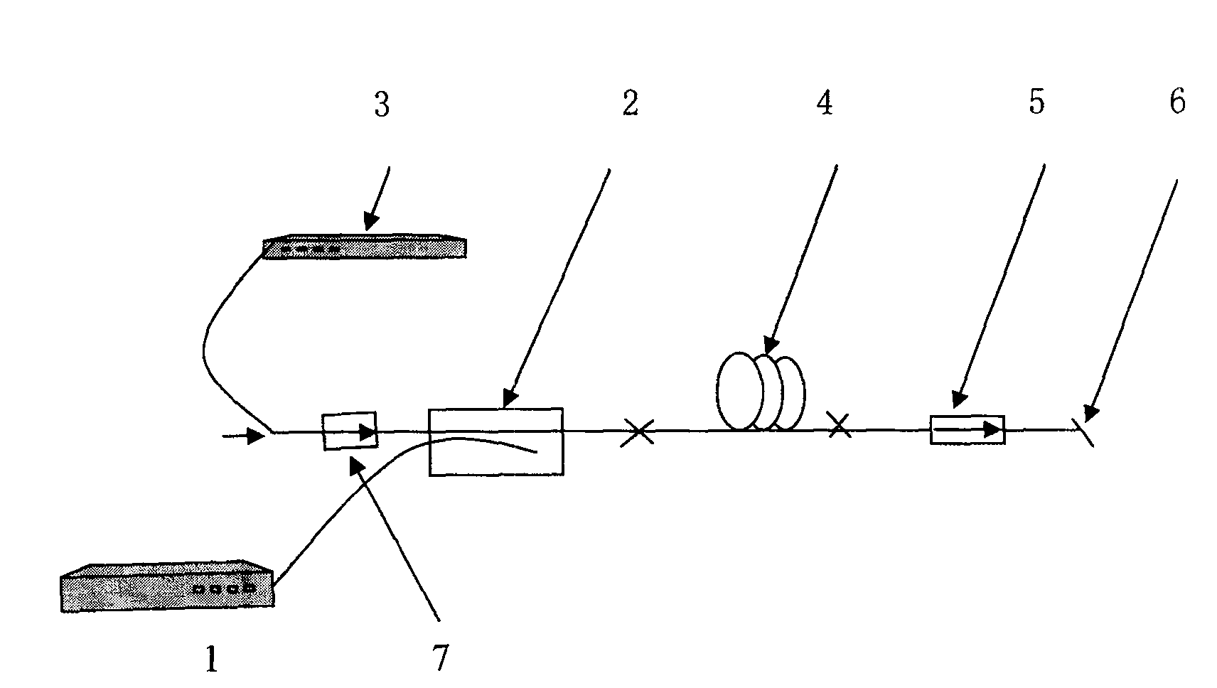
[0017] see first figure 1 , figure 1 It is a schematic diagram of the overall structure of an embodiment of a 1053nm high-power, narrow-linewidth signal source embodiment of the present invention. It can be seen from the figure that the signal source with a wavelength of 1053nm, high power and narrow linewidth of the present invention is composed of: a multimode semiconductor laser 1 packaged in an optical flat panel is used as a pump source, and a linewidth of 10 -4 The 1053nm DFB laser 3 of nm is used as a weak signal seed light source, the output end of the multimode semiconductor laser 1 is fused with a pump end of the multimode pump beam combiner 2, and the DFB laser 3 is fused with a low power The isolator 7 is connected to the signal end of the multimode pump combi...


PUM


Abstract

This invention relates to a signal source with 1053nm wavelength, high power and narrow line width, which applies a multimode semiconductor packaged by an optical panel at the pump source and a 1053nm single vertical mode DFB laser with the line width of 10-4nm as the weak signal seed optical source, the output end of the semiconductor laser is melted to a pump end of a multimode pump beam synthesizer, the output tail fiber of which is melted to the input end of a double clad fiber amplifier doped with Yb, the output end of which is output by an 8deg. incline wire jumper.

Description

technical field [0001] The invention relates to a signal source realized by using ytterbium-doped double-clad optical fiber, especially a signal source with a wavelength of 1053nm, high power, and narrow line width, which has the advantages of narrow line width, high power, high signal-to-noise ratio, single longitudinal mode, it can be used as a signal source in occasions where both line width and power are strictly required. Background technique [0002] The signal source module implemented by optical fiber has the advantages of good beam quality, high efficiency, high stability, and compact structure, and has been widely used in communication, industry, and medical fields. Doped with Yb 3+ Silica fiber is a simple three-level system structure, with wide absorption spectrum, gain bandwidth and tuning range, high quantum efficiency, no excited state absorption, no concentration quenching, etc.; and the special structure of double-clad fiber, the pump The pump light can pr...

Claims


Application Information

Patent Timeline
Patent Type & Authority Patents(China)
IPC IPC(8): H04B10/155H04B10/291
Inventor 常丽萍范薇陈嘉琳王利孙安李国扬
Owner SHANGHAI INST OF OPTICS & FINE MECHANICS CHINESE ACAD OF SCI
Learn More