

Polarizing plate and liquid crystal display
A polarizer and polarizer technology, applied in the field of polarizers and liquid crystal displays, can solve the problem of not considering the uniformity of in-plane retardation value, and achieve the effect of uniform display quality
- Summary
- Abstract
- Description
- Claims
- Application Information
AI Technical Summary
Problems solved by technology
Method used
Image

Examples
preparation example Construction
[0069] A polarizing plate was prepared as follows. A preferred production method of the polarizer includes the steps of swelling, dyeing, hardening, stretching, drying, lamination with a protective film and drying after lamination. The order of the dyeing, hardening and stretching steps can be changed as desired. Two or more steps can be performed simultaneously. As taught in Japanese Patent No. 3331615, the hardening step is performed by washing with water.
[0070] The process is preferably carried out in the following order: swelling, dyeing, hardening / stretching, drying, lamination with protective film and drying after lamination. During or after these steps, a step of on-line detection of the surface condition may be provided.
[0071] The swelling step is preferably performed with water only. Aqueous boric acid solution can be used to swell PVA film to a controlled extent to obtain stabilized optical properties and prevent film shrinkage. The swelling temperature an...
Embodiment 1
[0534] 1. Preparation of Polarizer 1
[0535] A 75 μm thick PVA film with a degree of polymerization of 2400 was swelled in water at 30° C. for 40 seconds. The swollen PVA film was immersed in an aqueous solution containing 0.06% iodine and 6% potassium iodide at 30°C for 60 seconds, and then immersed in an aqueous solution containing 4% boric acid and 3% potassium iodide at 40°C for 60 seconds. While soaking the PVA film, stretch it longitudinally by 5.2 times. The moisture content of the PVA film immediately before stretching was 52%. Then, the longitudinally stretched PVA film was stretched 1.1 times in the transverse direction with a tenter. As a result, the final length is 5 times the original length. The stretched film was dried at 50° C. for 4 minutes to obtain a polarizer (named Polarizer 1).
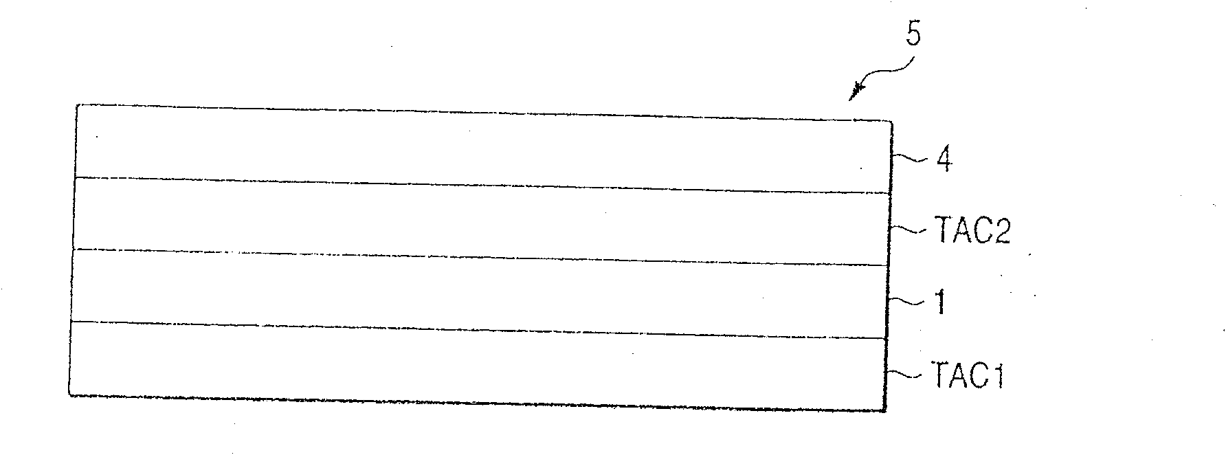
[0536] Film 1 (a cellulose acylate film prepared in advance) and a commercially available triacetyl cellulose film (TAC TD80U from Fuji Photo Film) were respectively dissolv...
Embodiment 2
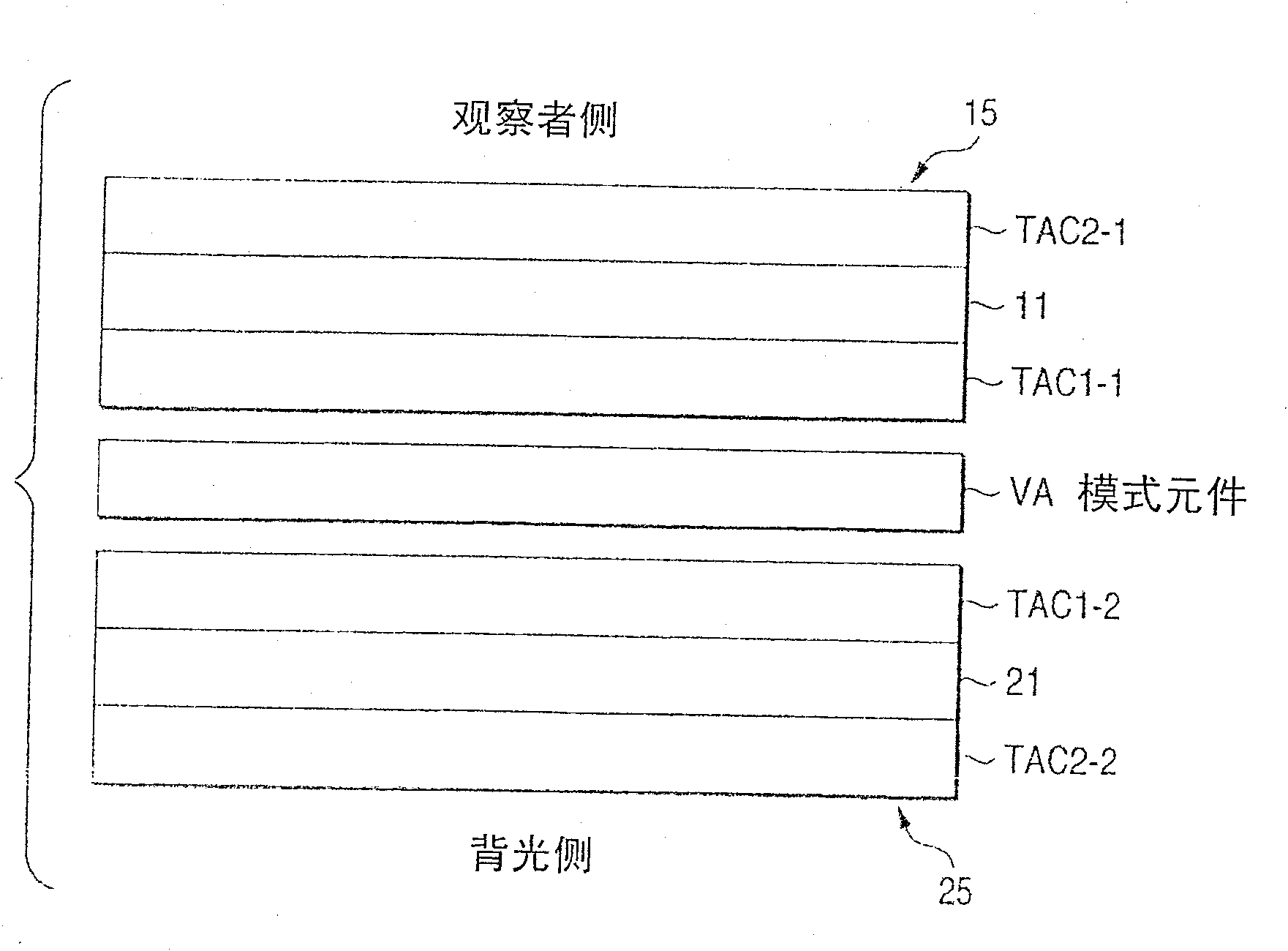
[0559] The polarizers on the viewing side and the backlight side of a VA mode LCD-television (LC-30AD1, manufactured by Sharp Corp.) were peeled off, and instead, the polarizers prepared in Example 1 and no viewing angle were provided according to the combinations in Table 4. A commercially available polarizing plate (HLC2-5618 from Sanritzu Corp.) was compensated for the film. The polarizer on the viewing side was installed with its absorption axis parallel to the horizontal direction of the LCD panel, and the polarizer on the backlight side was installed with its absorption axis coincident with the vertical direction of the panel. The polarizers were bonded with their adhesive side facing the liquid crystal cell.
[0560] After the releasable protective sheet was peeled off, the viewing angle of the LCD-television displayed in 8 levels from black (L1) to white (L8) was measured with a contrast meter (EZContrast 160D, manufactured by ELDIM) (with a contrast ratio of 10 or mor...
PUM
| Property | Measurement | Unit |
|---|---|---|
| thickness | aaaaa | aaaaa |
| water contact angle | aaaaa | aaaaa |
| particle diameter | aaaaa | aaaaa |
Abstract
Description
Claims
Application Information