Microwave resonance cavity

A microwave resonant cavity and integrated technology, which is applied in the direction of resonators, waveguide devices, electrical components, etc., can solve the problems of unsatisfactory plasma uniformity, poor plasma uniformity, inconvenient disassembly and maintenance, etc., and achieve the improvement of large-area processing capacity , prevent microwave leakage, easy maintenance effect

Inactive Publication Date: 2009-12-23
XIDIAN UNIV
View PDF4 Cites 0 Cited by
  • Summary
  • Abstract
  • Description
  • Claims
  • Application Information

AI Technical Summary

Problems solved by technology

The plasma uniformity of most microwave electron cyclotron resonance devices in the prior art is not ideal. The main reason is that microwave electron cyclotron resonance mostly uses 2.45GHz microwaves in TE10 mode, after passing through the waveform converter from TE10 mode to TE11 mode Converted to TE11 mode and then coupled into cylindrical resonant cavity through microwave window, or directly coupled into cylindrical resonant cavity through waveguide window to become TE11 mode
However, the transverse electric fields corresponding to the TE10 mode and the TE11 mode are not uniform, resulting in poor uniformity of the generated plasma.
At the same time, there is a contradiction between the microwave properties and the working area in the prior art, that is, the small-sized cavity has a single microwave mode and good electromagnetic characteristics, but it cannot realize large-area processing; increasing the cavity size can increase the processing size. However, the nature of microwave is poor, and the discharge is difficult to carry out. In severe cases, it may even cause ignition damage to components such as windows and cavities.
In addition, most of the existing technologies use spot welding to seal the microwave resonator to prevent microwave leakage, which is very inconvenient to disassemble and maintain

Method used


Image

  • Microwave resonance cavity
  • Microwave resonance cavity
  • Microwave resonance cavity

Examples


Embodiment Construction

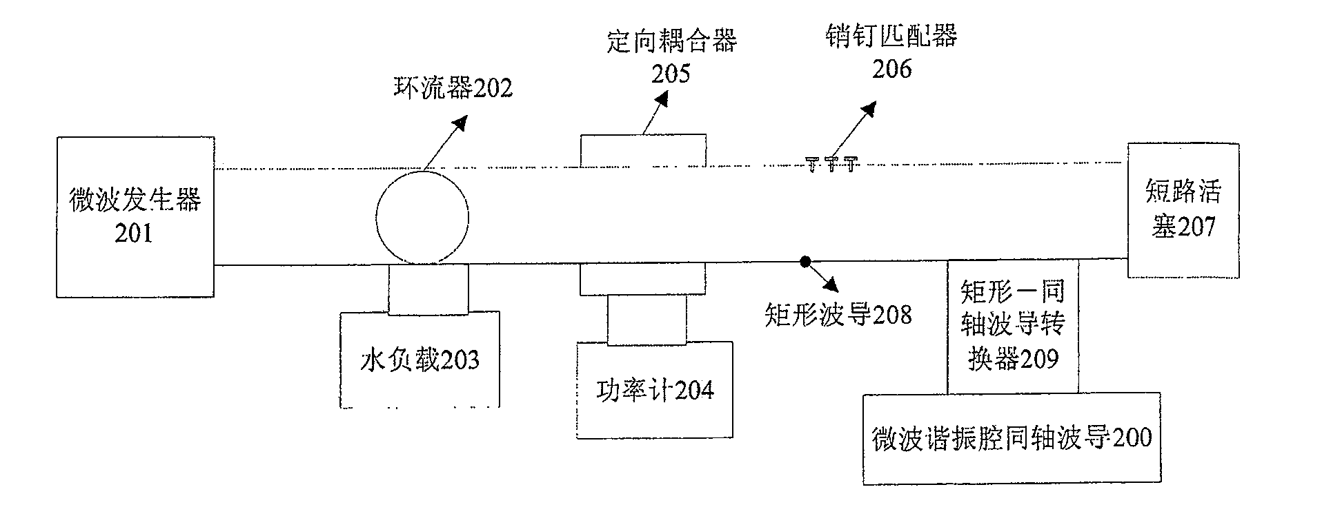
[0021] figure 2 A schematic diagram of the microwave power source and transmission system is given. The microwave power source and transmission system consists of a microwave generator 201, a circulator 202, a water load 203, a power meter 204, a directional coupler 205, a pin adapter 206, a short-circuit piston 207, a rectangular waveguide 208, and a rectangular-to-coaxial waveguide conversion device 209 and microwave resonator coaxial waveguide 200. The connection relationship of each part is: from left to right, the rectangular waveguide 208 is respectively connected with the microwave generator 201, the circulator 202, the directional coupler 205, the pin matching device 206, the rectangular-coaxial waveguide converter 209, and the short-circuit piston 207 connection; the reflection end of the circulator 202 is connected to the water load 203; the power meter 204 is connected to the directional coupler 205; the rectangular-coaxial waveguide converter 209 is connected to ...


PUM


Abstract

The invention discloses a microwave resonant cavity, which comprises: a coaxial waveguide and a dielectric window, wherein the coaxial waveguide (200) adopts an integrated structure composed of a circular waveguide and a tapered waveguide, and the coaxial waveguide A flange (700) is fixed below, a circular window is opened in the middle of the flange, a sealing groove (903) is opened outside the window, a sealing ring is arranged in the sealing groove, and a medium window (902) is fixed on the sealing ring. A fixed rubber ring (901) is provided between the dielectric window and the inner wall of the flange, and a non-magnetic tray (600) is provided on the dielectric window, and a choke coil ( 800) to connect. The upper outer edge of the flange is connected with the lower outer edge of the outer conductor of the coaxial waveguide through threads, and the lower outer edge of the flange is connected with the upper outer edge of the process chamber through threads. The invention has the advantages of uniform microwave electric field distribution, large cavity processing size, convenient disassembly and maintenance, and can be used to provide microwave electric field for electron cyclotron resonance plasma equipment.

Description

technical field [0001] The invention relates to components of electron cyclotron resonance plasma equipment, specifically a microwave resonant cavity, which is used to provide microwave electric field for electron cyclotron resonance plasma equipment. Background technique [0002] Electron cyclotron resonance ECR plasma has the advantages of low working pressure, high density, high ionization rate, uniform large area, simple process equipment, stable operation and easy control of parameters, etc. It can realize low-temperature, efficient and pollution-free surface treatment. There is a huge application potential in IC manufacturing process. ECR means that when the input microwave frequency ω is equal to the electron cyclotron frequency ω ce Resonance occurs when microwave energy is coupled to electrons, and the energy-gained electrons ionize neutral gas molecules to generate a discharge. By adjusting the magnetic field, the resonance condition is reached in a certain area ...

Claims


Application Information

Patent Timeline
Patent Type & Authority Patents(China)
IPC IPC(8): H01P7/00H05H1/46
Inventor 杨银堂俞书乐汪家友陈光族付俊兴
Owner XIDIAN UNIV
Why Eureka
Try Eureka