Microwave resonance cavity

A microwave resonant cavity, integrated technology, applied in resonator, plasma, waveguide-type devices and other directions, can solve the problems of unsatisfactory plasma uniformity, poor plasma uniformity, inconvenient disassembly and maintenance, etc., to improve large-area processing capacity , The effect of preventing microwave leakage and convenient disassembly

Inactive Publication Date: 2008-02-20
XIDIAN UNIV
View PDF0 Cites 21 Cited by
  • Summary
  • Abstract
  • Description
  • Claims
  • Application Information

AI Technical Summary

Problems solved by technology

The plasma uniformity of most microwave electron cyclotron resonance devices in the prior art is not ideal. The main reason is that microwave electron cyclotron resonance mostly uses 2.45GHz microwaves in TE10 mode, after passing through the waveform converter from TE10 mode to TE11 mode Converted to TE11 mode and then coupled into cylindrical resonant cavity through microwave window, or directly coupled into cylindrical resonant cavity through waveguide window to become TE11 mode
However, the transverse electric fields corresponding to the TE10 mode and the TE11 mode are not uniform, resulting in poor uniformity of the generated plasma.
At the same time, th

Method used


Image

  • Microwave resonance cavity
  • Microwave resonance cavity
  • Microwave resonance cavity

Examples


Embodiment Construction

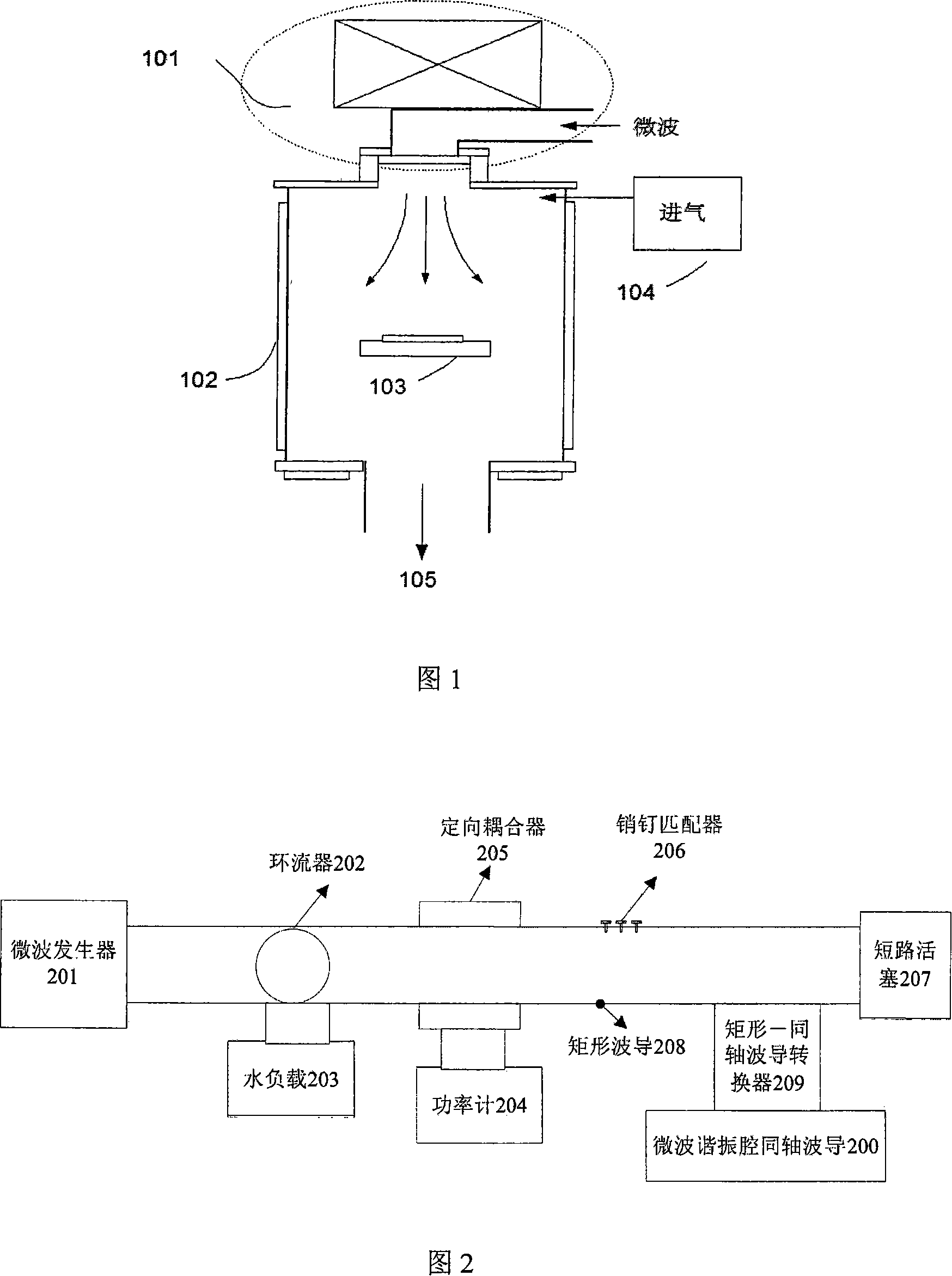
[0021] Figure 2 shows a schematic diagram of the microwave power source and transmission system. The microwave power source and transmission system consists of a microwave generator 201, a circulator 202, a water load 203, a power meter 204, a directional coupler 205, a pin adapter 206, a short-circuit piston 207, a rectangular waveguide 208, and a rectangular-to-coaxial waveguide conversion device 209 and microwave resonator coaxial waveguide 200. The connection relationship of each part is: from left to right, the rectangular waveguide 208 is respectively connected with the microwave generator 201, the circulator 202, the directional coupler 205, the pin matching device 206, the rectangular-coaxial waveguide converter 209, and the short-circuit piston 207 connection; the reflection end of the circulator 202 is connected to the water load 203; the power meter 204 is connected to the directional coupler 205; the rectangular-coaxial waveguide converter 209 is connected to the c...


PUM

PropertyMeasurementUnit
Angleaaaaaaaaaa

Abstract

The utility model discloses a microwave resonant cavity, comprising a coaxial waveguide and a medium window, wherein the coaxial waveguide 200 is an integrative unit comprising a circular waveguide tube and a conical waveguide tube; a flange 700 is fixed below the coaxial waveguide and is provided with a circular window at the center; a sealing groove 903 is arranged on the outer side of the window; a sealing ring is arranged in the sealing groove ; the medium window 902is fixed on the sealing ring; a fixed rubber ring 901 is fixed between the inner wall of the medium window and the flange; the medium window is provided with a non-magnetic tray 600, the internal conductor 502 of the coaxial waveguide is connected with the non-magnetic tray 600 through a choke 800; the upper external edge of the flange is in thread connection with the lower external edge of the external conductor of the coaxial waveguide; and the lower external edge of the flange is connected with the upper external edge of the craft chamber through thread. The utility model has the advantages of even distribution of the microwave electric field, big chamber processing size and easy disassembly and maintenance and is used for providing microwave electric field for the electron cyclotron resonance plasma devices.

Description

technical field [0001] The invention relates to components of electron cyclotron resonance plasma equipment, specifically a microwave resonant cavity, which is used to provide microwave electric field for electron cyclotron resonance plasma equipment. Background technique [0002] Electron cyclotron resonance ECR plasma has the advantages of low working pressure, high density, high ionization rate, uniform large area, simple process equipment, stable operation and easy control of parameters, etc. It can realize low-temperature, efficient and pollution-free surface treatment. There is a huge application potential in IC manufacturing process. ECR means that when the input microwave frequency ω is equal to the electron cyclotron frequency ω ce Resonance occurs when microwave energy is coupled to electrons, and the energy-gained electrons ionize neutral gas molecules to generate a discharge. By adjusting the magnetic field, the resonance condition is reached in a certain area ...

Claims


Application Information

Patent Timeline
IPC IPC(8): H01P7/00H05H1/46
Inventor 杨银堂俞书乐汪家友陈光族付俊兴
Owner XIDIAN UNIV
Why Eureka
Try Eureka