Separate floor type air conditioner filtering net automatic cleaning device

An automatic cleaning and filter technology, applied in the fields of dispersed particle filtration, air conditioning systems, heating methods, etc., can solve problems such as increased energy consumption, inconvenience for users, clogging of filter meshes and ventilation, etc. Low, simple structure effect

Inactive Publication Date: 2010-01-20
GREE ELECTRIC APPLIANCES INC
View PDF3 Cites 0 Cited by
  • Summary
  • Abstract
  • Description
  • Claims
  • Application Information

AI Technical Summary

Problems solved by technology

[0002] At present, the dust removal method of most air conditioner filters is to manually remove the filter for cleaning. Although the purpose of dust removal can be achieved, it brings inconvenience to users.
Ordinary split floor-standing air conditioners set the filter near the air inlet for a period of time, and the dust accumulated on the filter will cause the mesh to be clogged and cause poor ventilation. If it cannot be cleaned in time, it will affect the cooling and heating effect and increase energy efficiency. consumption

Method used


Image

  • Separate floor type air conditioner filtering net automatic cleaning device
  • Separate floor type air conditioner filtering net automatic cleaning device
  • Separate floor type air conditioner filtering net automatic cleaning device

Examples


Embodiment 1

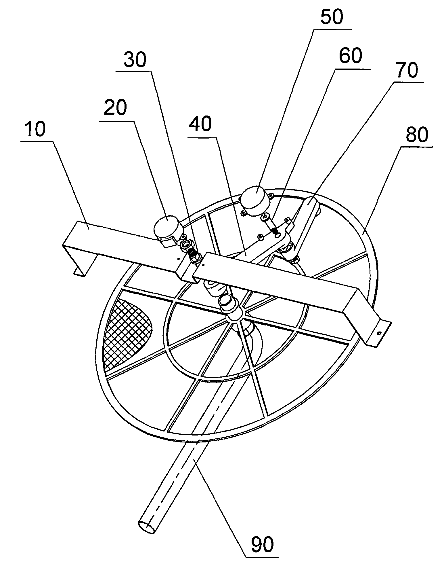
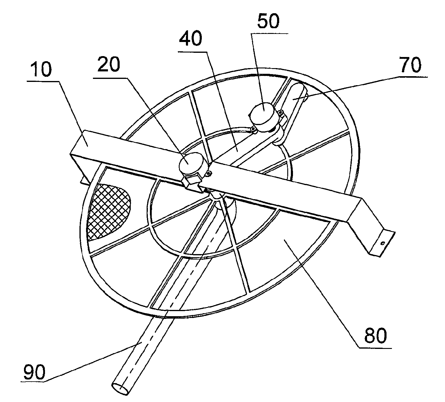
[0020] When the filter screen cleaning button on the air conditioner is connected, the motor a20, the motor b50 and the dust suction device start simultaneously. Driven by the motor a20, the suction pipe a 40 is linked with the suction pipe b, the motor b, and the connector b to make a 360-degree continuous rotation around the center of the motor a20. degree rotation. The two motors rotate at a certain speed, so that the suction nozzle at the end of the suction pipe b70 scans the circular area in front of the filter screen 80, and the purpose of removing dust on the filter screen is achieved by the action of the dust suction device.

Embodiment 2

[0022] When the filter screen cleaning button on the air conditioner is connected, the motor a20, the motor b50 and the dust suction device start simultaneously. Driven by the motor a20, the suction pipe a 40 links with the suction pipe b, the motor b, and the connector b to make a 360-degree reciprocating rotation around the center of the stepping motor a20. rotate. The two motors rotate at a certain speed respectively, so that the suction nozzle at the end of the suction pipe b70 scans the circular area in front of the filter screen 80, and the purpose of removing the accumulated dust on the filter screen is achieved by the action of the dust suction device.

Embodiment 3

[0024] When the filter screen cleaning button on the air conditioner is connected, the motor a20, the motor b50 and the dust suction device start simultaneously. Driven by the motor a20, the suction pipe a40 links with the suction pipe b, the motor b, and the connector b to continuously rotate 360 ​​degrees around the center of the motor a20. The two motors rotate at a certain speed respectively, so that the suction nozzle at the end of the suction pipe b70 scans the circular area in front of the filter screen 80, and the purpose of removing the accumulated dust on the filter screen is achieved by the action of the dust suction device.


PUM


Abstract

The invention discloses an automatic cleaner for a filter screen of a separated floor-type air conditioner which consists of a mounting board, a motor a, a connector a, a sucker a, a motor b, a connector b, a sucker b, the filter screen, a connection pipe and a dust sucker; the device is arranged in the front of the filter screen of the air conditioner and rotates on the vertical position which is equidistant relatively to the front of the filter screen by taking the center of the filter as a circular center for leading a suction nozzle to scan the round area in front of the filter screen and achieving the object of removing the dust accumulated on the filter screen by relaying on the effect of the dust sucker. The device has simple structure, is easy to realize production and can omit the trouble for manually cleaning the filter screen of users.

Description

technical field [0001] The invention relates to the field of air conditioners, in particular to a split floor type air conditioner with an automatic cleaning filter screen device. Background technique [0002] At present, the dust removal method of most air conditioner filter screens is to manually remove the filter screen for cleaning. Although the purpose of dust removal can be achieved, it brings inconvenience to users. Ordinary split floor-standing air conditioners set the filter near the air inlet for a period of time, and the dust accumulated on the filter will cause the mesh to be blocked and cause poor ventilation. If it cannot be cleaned in time, it will affect the cooling and heating effect and increase energy efficiency. consumption. Contents of the invention [0003] The purpose of the present invention is to provide a simple structure, easy to implement automatic filter screen cleaning device, eliminating the trouble of manual cleaning of the filter screen by...

Claims


Application Information

Patent Timeline
Patent Type & Authority Patents(China)
IPC IPC(8): F24F3/16B01D46/10F24F1/00F24F1/02F24F13/28
Inventor 张辉钟明生孟宪运刘北泉王朝新邹云辉甄伟磊
Owner GREE ELECTRIC APPLIANCES INC
Why Eureka
Try Eureka