Irrigation device

An irrigation device and filter device technology, applied in watering devices, water supply devices, drinking water devices, etc., can solve the problem of inability to remove dead leaves accumulated on the surface of the filter screen, reduce irrigation energy consumption, save irrigation water, and enhance efficiency. Effect

Inactive Publication Date: 2021-06-22
绍兴市米莉农业科技有限公司
View PDF1 Cites 0 Cited by
  • Summary
  • Abstract
  • Description
  • Claims
  • Application Information

AI Technical Summary

Problems solved by technology

[0006] Aiming at the deficiencies of the prior art, the present invention provides an irrigation device, which solves the problem that the existing device cannot remove the dead leaves accumulated on the surface of the filter screen, effectively prevents the collection of rainwater from being affected by too many dead leaves or sundries, and improves the irrigation efficiency. Improve the reuse rate of rainwater collection, avoid debris blocking the water storage tank and hinder irrigation operations, achieve the purpose of automatically cleaning the filter screen, and will not cause excessive load on the filter device, further improving the service life of the filter device

Method used


Image

  • Irrigation device
  • Irrigation device
  • Irrigation device

Examples


Embodiment 1

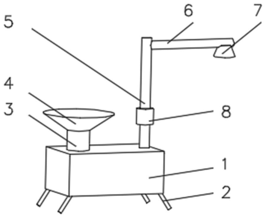
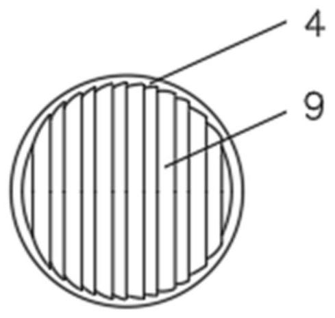
[0035] see Figure 1-3 , the present invention provides a technical solution: an irrigation device, including a water storage tank 1, the bottom of the water storage tank 1 is evenly equipped with a bracket 2, the top of the water storage tank 1 is connected with a water storage pipe 3, and the water storage pipe 3 is far away from the One end of the water storage tank 1 is connected with a water inlet 4, the side of the water storage tank 1 close to the water storage pipe 3 is connected with a water outlet pipe 5, and the end of the water outlet pipe 5 far away from the water storage tank 1 is connected with a connecting pipe 6, and the connecting pipe 6 is far away from the water storage tank 1. One end of the water outlet pipe 5 is equipped with a shower nozzle 7 , a side of the water outlet pipe 5 is equipped with a water pump 8 near the position of the water storage tank 1 , and a side of the water outlet 4 is equipped with a filter device 9 .

[0036] The filtering devic...

Embodiment 2

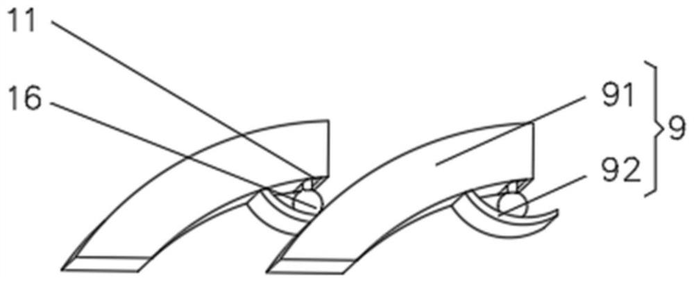
[0040] see Figure 1-6 , the present invention provides a technical solution: on the basis of Embodiment 1, a groove 11 is opened on the side of the baffle plate 91 close to the filter screen 92, and the inner wall of the groove 11 is symmetrically installed with a limit block 12, and between the limit block 12 A slide bar 13 is fixedly connected between them, the outside of the slide bar 13 is provided with a slide block 14, the outside of the slide block 14 is provided with a connecting rod 15, and the end of the connecting rod 15 away from the slide block 14 is fixedly connected with a push ball 16.

[0041] One side of the push ball 16 is provided with a chute 17, the inner wall of the chute 17 is fixedly connected with a connecting rope 18, and the end of the connecting rope 18 away from the chute 17 is fixedly connected with the filter screen 92, and a push plate is installed on one side of the connecting rope 18 19.

[0042]Filter screen 92 is equipped with blade 20 ne...

Embodiment 3

[0048] see Figure 1-7 , the present invention provides a technical solution: on the basis of Embodiment 2, a device groove 21 is provided on one side of the push plate 19, a sliding groove 22 is provided on the inner wall of the device groove 21, and a slide plate is slidably connected to one side of the sliding groove 22 23. A second spring 24 is installed on one side of the slide plate 23, and one end of the second spring 24 away from the slide plate 23 is fixedly connected to the inner wall of the device groove 21, and the side of the slide plate 23 away from the second spring 24 is rotatably connected with a rotating plate 25.

[0049] When in use, when the push plate 19 is pulled by the connecting rope 18, the pushing ball 16 drives the connecting rope 18 to shake and rotate, so that the rotating plate 25 squeezes the sliding plate 23 due to the centrifugal force during rotation, and the second spring 24 is squeezed into the device groove. Inside the 21, through the inst...


PUM


Abstract

The invention discloses an irrigation device and relates to the technical field of irrigation. The irrigation device comprises a water storage tank, supports are evenly installed at the bottom of the water storage tank, the top of the water storage tank communicates with a water storage pipe, the end, away from the water storage tank, of the water storage pipe communicates with a water receiving opening, the purpose of collecting rainwater is achieved through communication of the water receiving opening and the water storage tank, the side, close to the water storage pipe, of the water storage tank communicates with a water outlet pipe, the end, away from the water storage tank, of the water outlet pipe communicates with a connecting pipe, a spray head is installed at the end, away from the water outlet pipe, of the connecting pipe, a water suction pump is installed at the position, close to the water storage tank, of one side of the water outlet pipe, a filtering device is installed on one side of a water receiving opening, a pushing device is installed in the filtering device, the filtering device comprises a baffle, and the baffle is a curved plate. According to the irrigation device, the purpose of removing dead leaves accumulated on the surface of the filter screen is achieved, and the situation that rainwater collection is affected by too many dead leaves or sundries is effectively prevented.

Description

technical field [0001] The invention relates to the technical field of irrigation, in particular to an irrigation device. Background technique [0002] As a natural resource bestowed by nature, rainwater is often neglected by people. In residential areas, rainwater is generally discharged directly into rivers through runoff or rainwater pipes, or even discharged into sewage pipes and sent to sewage treatment plants. , increased the workload of sewage treatment plants. In areas where water resources are scarce, it is especially important to pay attention to the use of rainwater, which can largely solve some of the contradictions in water use. Rainwater recycling is to collect, process, store and utilize natural rainfall. The rainwater recycling system is a series of supporting structures and assembly equipment. The existing rainwater recovery system has the problems of poor filtering effect, turbid water quality and many sundries when rainwater is reused. [0003] For exam...

Claims


Application Information

Patent Timeline
Patent Type & Authority Applications(China)
IPC IPC(8): A01G25/02B01D29/03B01D29/64E03B3/02
CPCA01G25/02B01D29/03B01D29/6484E03B3/02Y02A20/108
Inventor 王方方
Owner 绍兴市米莉农业科技有限公司
Why Eureka
Try Eureka