Elliptical sealing surface for butterfly valve

A sealing surface, valve sealing technology, applied in the direction of valve lift, valve device, valve details, etc., can solve the problems of increased complexity of installation and adapter structure

Inactive Publication Date: 2010-02-17
FISHER CONTROLS INT LLC
View PDF11 Cites 2 Cited by
  • Summary
  • Abstract
  • Description
  • Claims
  • Application Information

AI Technical Summary

Problems solved by technology

This complex mounting and adapter configuration adds undesirable overall manufacturing cost and assembly complexity to prior art rotary valves

Method used


Image

  • Elliptical sealing surface for butterfly valve
  • Elliptical sealing surface for butterfly valve
  • Elliptical sealing surface for butterfly valve

Examples


Embodiment Construction

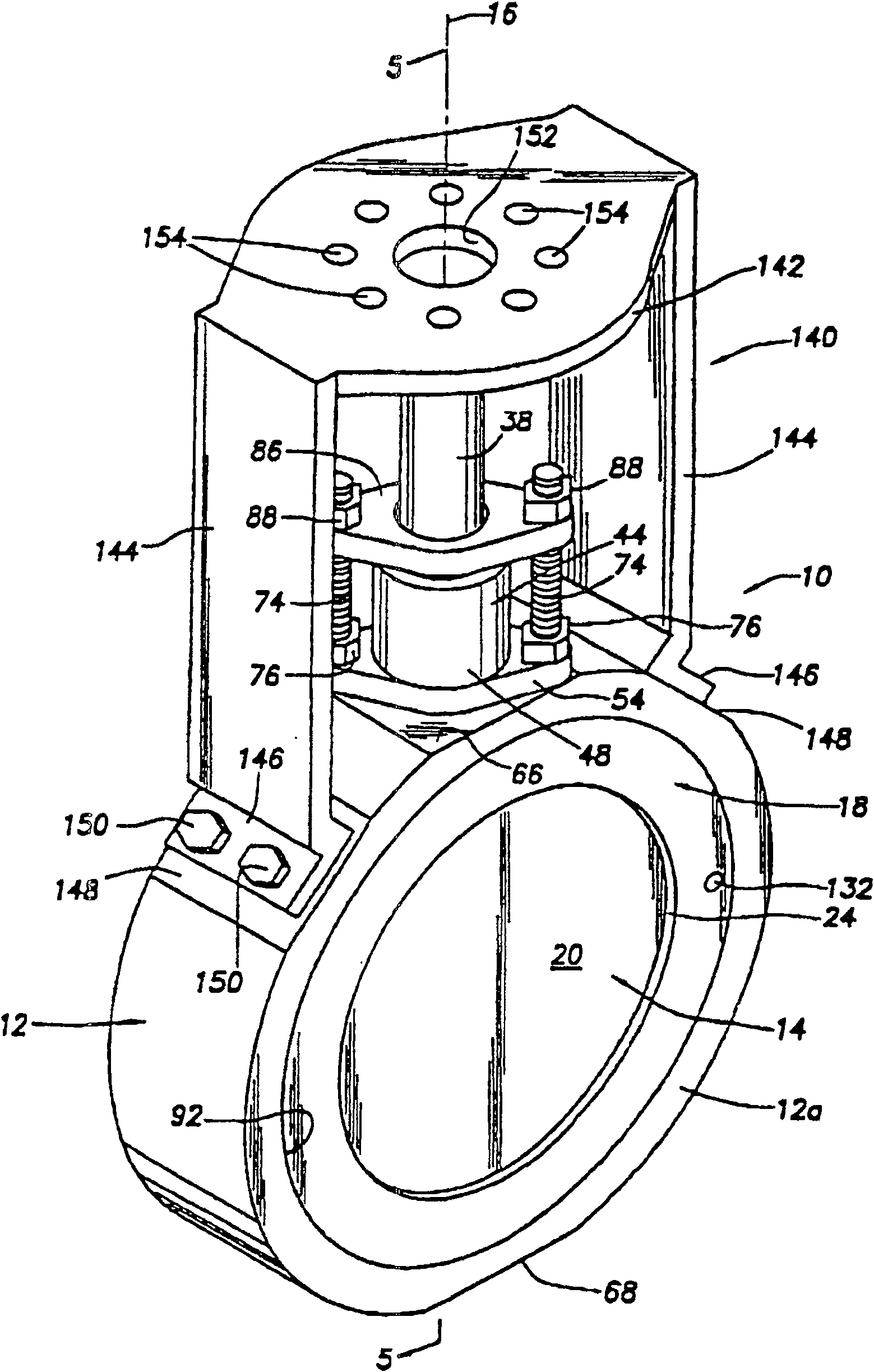
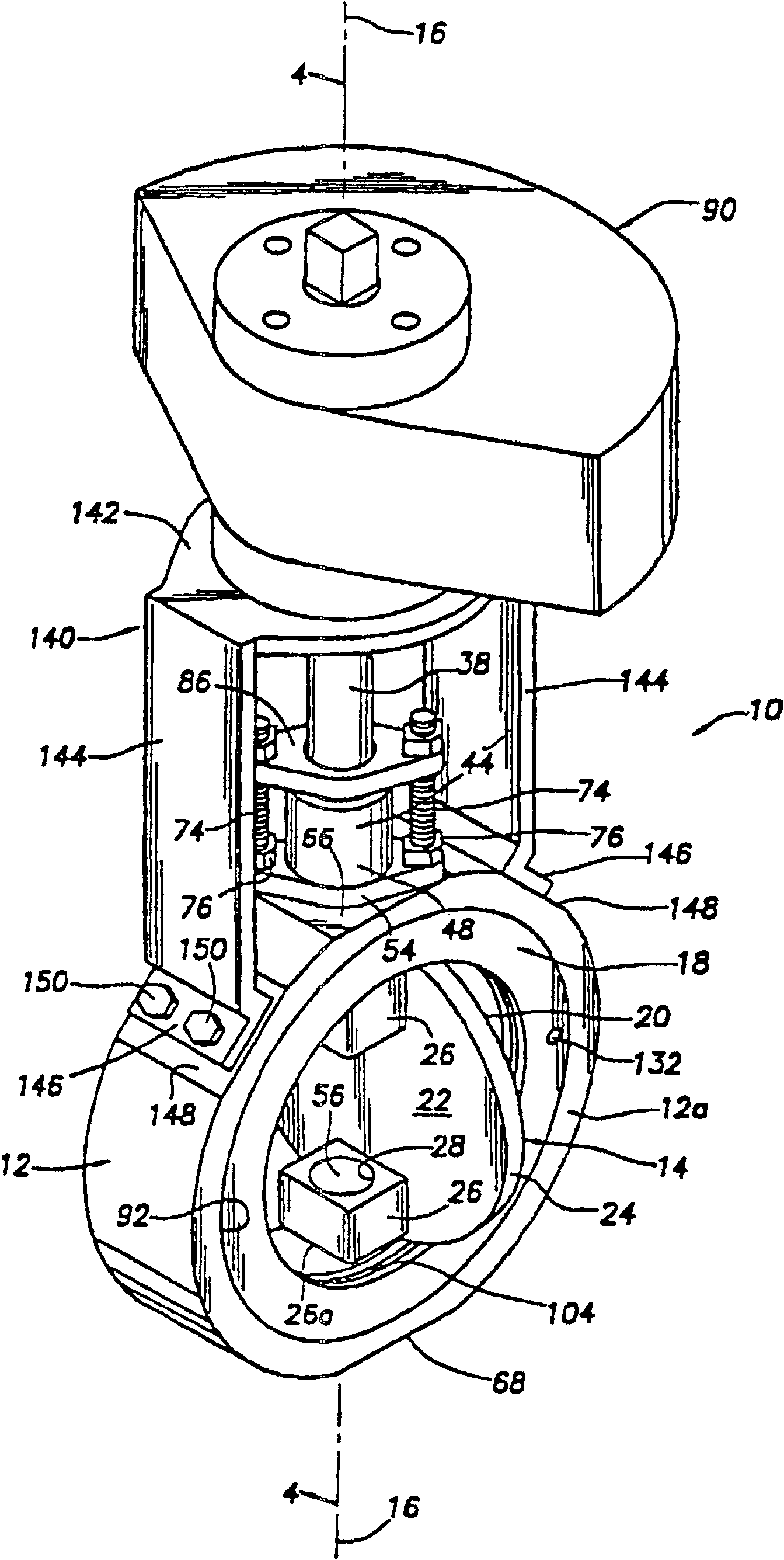
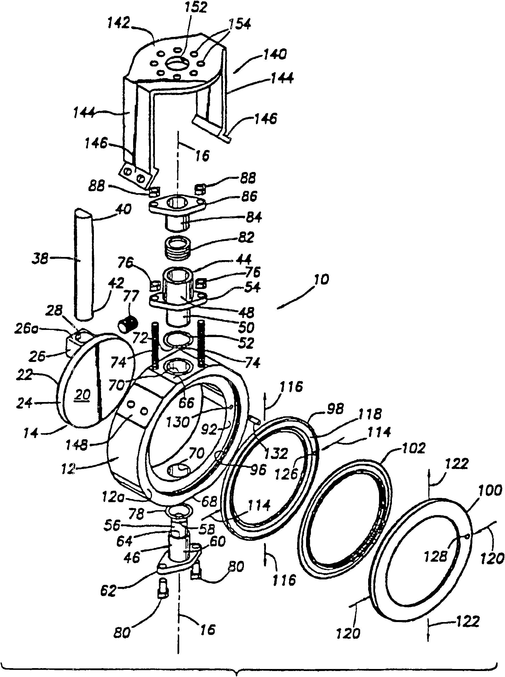
[0039] Figure 1-3 One embodiment of a rotary valve 10 is shown, commonly referred to as a "butterfly" valve, comprising a generally annular metal body portion 12, a metal closure disc 14 and an annular sealing sleeve structure 18, wherein the The metal closure disc 14 is in the closed position and the open position (respectively in figure 1 and 2 shown in ) about an axis 16 extending diametrically through the body portion 12 . figure 1 The valve disc 14 is shown mating with a sealing sleeve structure 18 in a closed position, preventing fluid flow through the interior of the body portion 12 and operably connected to a conduit portion (not shown) on the opposite side of the body portion 12 . Alternatively, in figure 2 Illustrated in is the valve disc 14 in the open position, which allows fluid to flow through the interior of the valve body 12 and the conduits operably connected to the valve body 12 .

[0040] turn to Figure 7-8B The valve disc 14 has a body portion with ...


PUM


Abstract

A reduced component wear valve is comprised of a valve body having a passage therethrough and a disc attached to a rotatable shaft. The disc is utilized with a seal forming a gap between the disc andthe seal proximate to the rotational axis of the disc. When the disc is in the open position, the seal major axis is greater then the disc diameter and they do not touch. As the disc rotates to near closure, the disc perimeter engages the minor axis of the seal (which is smaller than the disc diameter), and the disc stretches the seal in the minor axis direction thus decreasing the major axis suchthat the gap is closed. The seal can be pre-formed in an elliptical shape or it can be formed into an elliptical shape by a retaining mechanism. The seal may be a single-piece or a multi-piece assembly press-fit into the valve body. Zero or light disc to seal contact during the majority of the valve disc rotation minimizes valve seal wear and rotational friction.

Description

[0001] Cross References to Related Applications [0002] This application claims priority to co-pending U.S. Patent Application 09 / 675684, filed September 29, 2000, and co-pending U.S. Patent Application 10 / 005543, filed November 8, 2001, which was filed on January 2001 A divisional application of US patent application 09 / 772782 filed on the 30th, which is a divisional application of US patent application 09 / 441394 filed on November 16, 1999, now US6213141B1. technical field [0003] The present invention relates generally to a rotary valve or "butterfly" valve and methods for making the same, and more particularly to reducing friction and improving the sealing and wear characteristics of the valve. Background technique [0004] Rotary valves (commonly referred to as "butterfly" valves) typically have a valve disc that is rotatably driven between an open position and a closed position about a central axis extending diametrically through typically The interior of the annular...

Claims


Application Information

Patent Timeline
Patent Type & Authority Patents(China)
IPC IPC(8): F16K1/226F16K1/22F16K27/02
CPCF16K1/222F16K27/0218F16K1/2263F16K1/24Y10T137/0525
Inventor 菲利普·W·埃格尔斯顿詹姆斯·L·劳恩斯伯里威尔伯·D·赫琴斯
Owner FISHER CONTROLS INT LLC
Why Eureka
Try Eureka