Magnetorheological finishing device for super large caliber aspheric surface optical part

A technology of magnetorheological polishing and optical parts, which is applied in the field of magnetorheological polishing, can solve problems such as unguaranteed, fixed workpieces, and unacceptable costs, so as to avoid fluctuations in flow and velocity, ensure processing accuracy, and achieve good processing The effect of precision

CN100593456CInactive Publication Date: 2010-03-10NAT UNIV OF DEFENSE TECH
7 Cites 0 Cited by

Patent Information

Authority / Receiving Office
CN · China
Patent Type
Patents(China)
Current Assignee / Owner
Publication Date
2010-03-10
Estimated Expiration
Not applicable · inactive patent

Smart Images

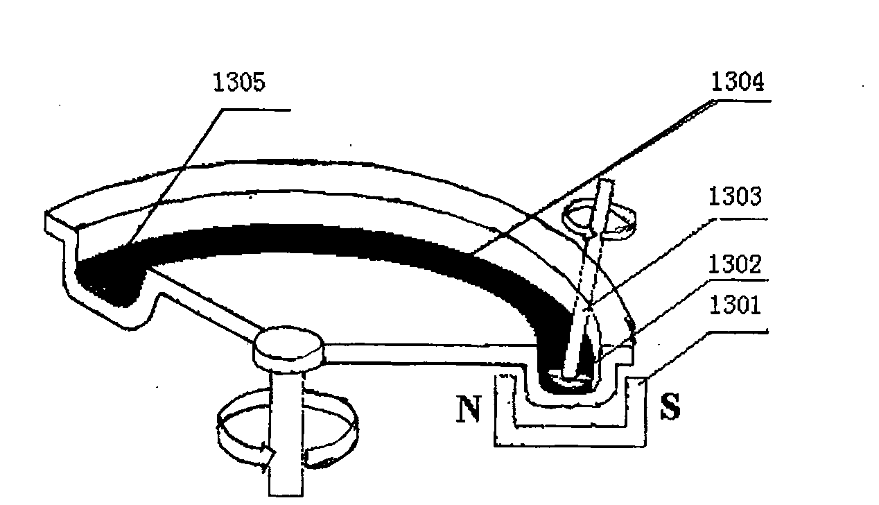
  • Figure 1
    Figure 1
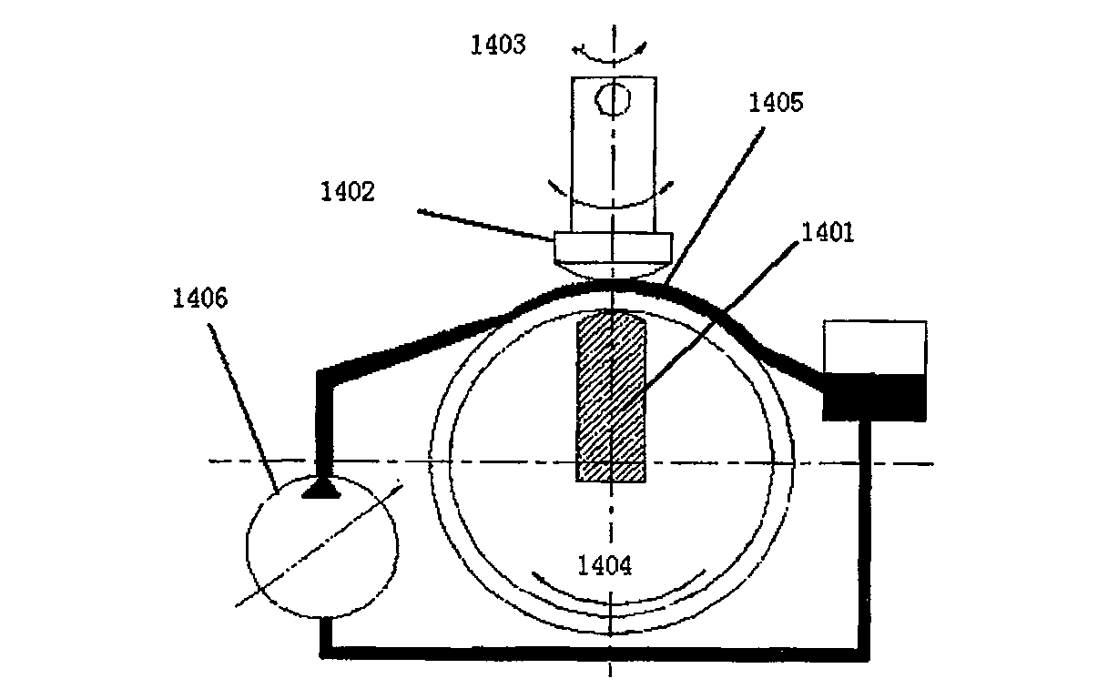
  • Figure 2
    Figure 2
  • Figure 3
    Figure 3
Patent Text Reader

Abstract

The invention relates to a magnetic rheological polishing device used in an aspheric optical part with a super large caliber, comprising a machine tool, a magnetic rheological polishing device and a control system which is connected with the above components. The machine tool comprises a lathe bed on which the work piece to be processed is placed, an X axial linear motion mechanism is arranged onthe two sides of the lathe bed, a movable portal is fixed on a slider of the X axial linear motion mechanism, a Y axial linear motion mechanism is arranged on a cross beam of the movable portal, a Z axial linear motion mechanism is fixed on a slider of the Y axial linear motion mechanism, an A axial rotary table used for arranging the magnetic rheological polishing device is fixed on a slider of the Z axial linear motion mechanism, the magnetic rheological polishing device is fixed on the cross beam by a fourth linear motion mechanism, the two have opposite directions of motion, and the magnetic rheological polishing device is arranged right above the work piece to be processed. The device of the invention has the advantages of simple and compact structure, low cost, easy control and strong processing capacity, and can process the aspheric optical part with the super large caliber.
Need to check novelty before this filing date? Find Prior Art

Description

technical field

[0001] The invention mainly relates to the technical field of magnetorheological polishing, in particular to a magnetorheological polishing device for super-large diameter aspherical optical parts. Background technique

[0002] According to the Rayleigh criterion, the optical system can distinguish the limiting angular distance between two object points in the far field Δθ=1.22λ / D, where D is the effective aperture of the optical system, so increasing the effective aperture of the optical system is the key to improving the resolution of the optical system basic way. Taking the space camera as an example, the height of the satellite is about 200-300km. In order to obtain high resolution, the aperture of the camera is required to be at least 0.5-1m. In the field of space telescopes, the diameter of the primary mirror is also getting larger. For example, the EURO50 telescope of the European Southern Observatory has a primary mirror with a size of 50m and is com...

Examples

Embodiment Construction

[0093] The present invention will be described in further detail below in conjunction with the accompanying drawings and specific embodiments.

[0094] Such as Figure 4As shown, the magnetorheological polishing device for ultra-large diameter aspheric optical parts of the present invention includes a machine tool, a magnetorheological polishing system and a control system connected to each of the above components respectively. The machine tool includes a workpiece 10 for placing a workpiece to be processed. The bed 101 and the X-axis linear motion mechanism, the movable gantry, the Y-axis linear motion mechanism, the Z-axis linear motion mechanism, the fourth linear motion mechanism 513 and the A-axis turntable 9, the X-axis linear motion mechanism is arranged on On both sides of the bed 101, the two columns 401 of the movable gantry are respectively fixed on the sliders of the X-axis linear motion mechanism, the Y-axis linear motion mechanism is arranged on the gantry beam 4...