Double-firepot ring-shaped shaft kiln

A ring-shaped, shaft kiln technology, used in furnaces, vertical furnaces, lighting and heating equipment, etc., can solve problems such as output increase limitation, uneven airflow distribution, etc., to achieve the effects of good product quality, low failure rate, and low investment

Inactive Publication Date: 2007-07-18
北京嘉永会通能源科技有限公司
View PDF0 Cites 8 Cited by
  • Summary
  • Abstract
  • Description
  • Claims
  • Application Information

AI Technical Summary

Problems solved by technology

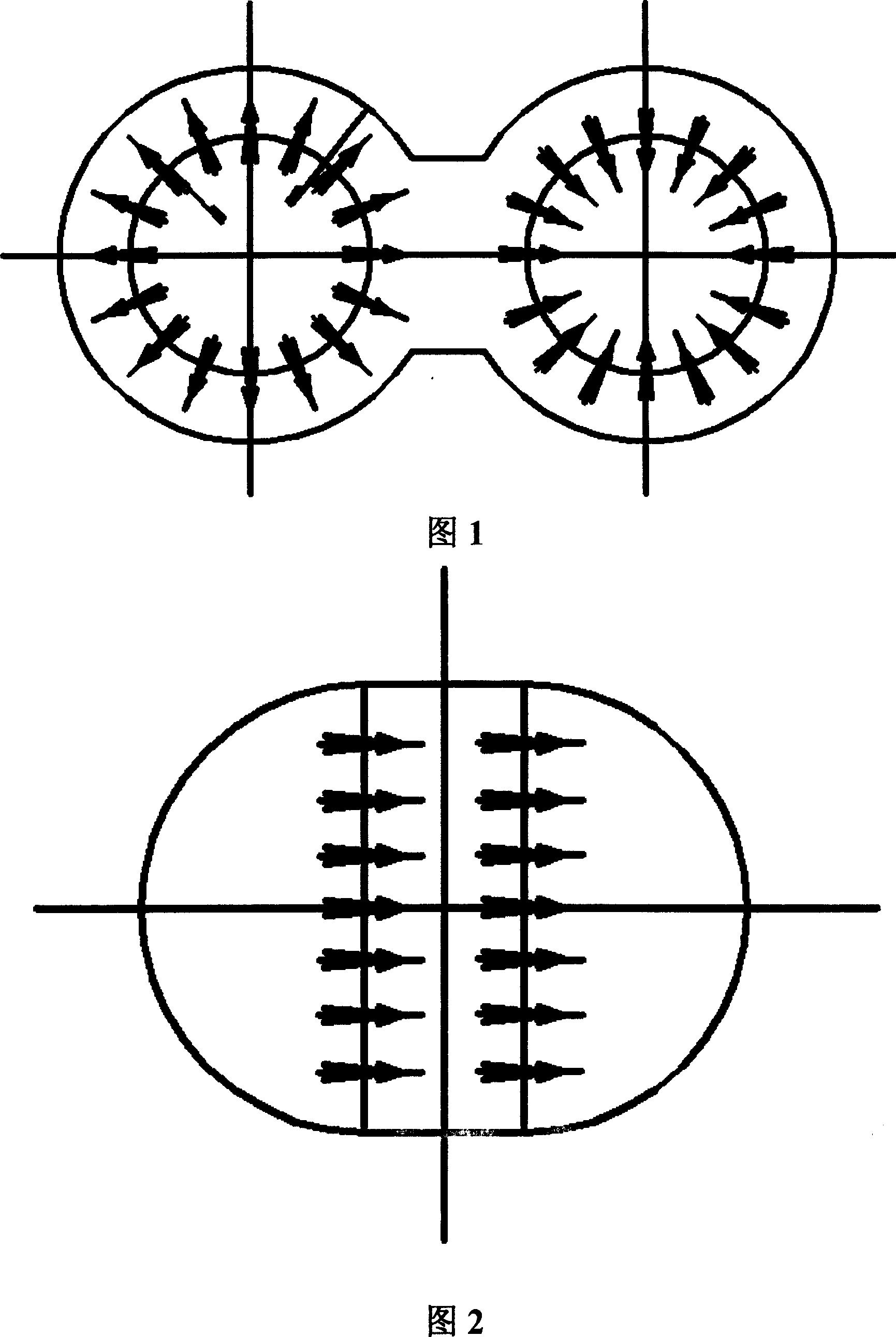
[0005] It can be seen from Figure 2 that the channel connecting the two kiln chambers of the vertical kiln chamber with a semicircular cross section is on the entire diameter, and the distances from the materials to the diameter of each part of the semicircle are quite different, so there is still airflow in the structure The distribution is uneven, so under the premise of ensuring product quality, the increase in production is also limited

Method used


Image

  • Double-firepot ring-shaped shaft kiln
  • Double-firepot ring-shaped shaft kiln

Examples


Embodiment Construction

[0015] Below in conjunction with accompanying drawing and specific embodiment the present invention is described in further detail:

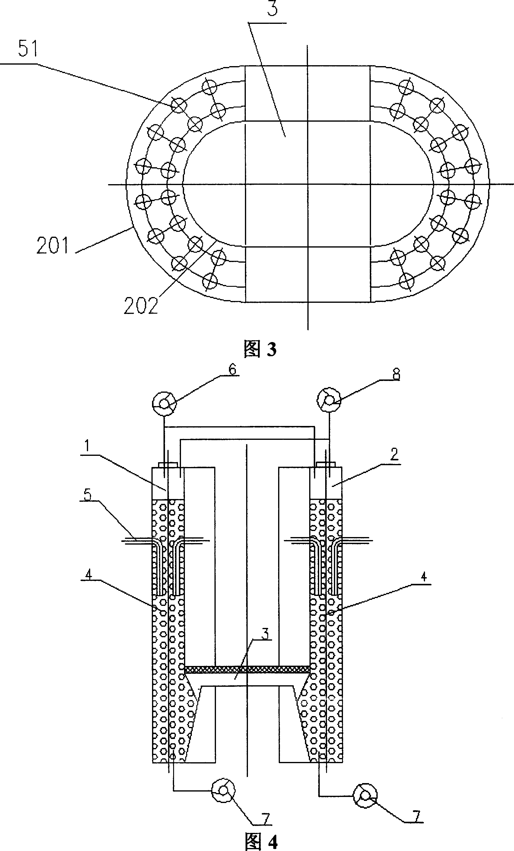
[0016] It can be seen from Figures 3 and 4 that the present invention includes: a first kiln tube 1 and a second kiln tube 2; the first kiln tube 1 and the second kiln tube 2 are connected together through a connecting channel 3; the first kiln tube 1 and the upper part of the second kiln tube 2 respectively include one or several feed openings and distributors (not shown in the figure), and one or several discharge ports are installed at the bottom of the first kiln tube 1 and the second kiln tube 2 (not shown in the figure); between the inner wall of the first kiln tube 1 and the second kiln tube 2, the burner nozzle 5 for the fuel required for the calcined material is included; between the first kiln tube 1 and the second kiln tube The top of 2 respectively includes a first blower 6 and an induced draft fan 8; when the first kiln barrel 1 is ...


PUM


Abstract

The invention relates to double-firepot ring-shaped shaft kiln. It includes the first and second kiln cylinders. Their sections are the same semi-ring which are formed by outer and inner circle radius, used to set massive ore, connected with each other along diameter direction by connecting passage. The invention can ensure shat kiln product quality and output, eliminate passage blockage, and realize low investment and failure rate for device.

Description

technical field [0001] The invention relates to a heat storage kiln for calcining lumpy bulk materials, in particular to a double-chamber shaft kiln. Background technique [0002] Judging from the existing regenerative kilns for calcining lumpy bulk materials, the cross-sections of the kilns mainly include the following types: one is square; the other is circular; the third is semicircular. [0003] The kiln with square section is only limited to the situation of low output, this is because due to structural limitations, the ratio of the long side to the short side of the square section cannot be too large. If the output of the kiln is increased, the long side and the short side must be enlarged at the same time to increase the calcination area and thereby increase the output. According to the existing experience, in this case, the gas bias flow is too large, resulting in calcination. Product quality is reduced. [0004] It can be seen from Figure 1 that the circular kiln ...

Claims


Application Information

Patent Timeline
Patent Type & Authority Applications(China)
IPC IPC(8): F27B1/02
Inventor 高静涛
Owner 北京嘉永会通能源科技有限公司
Why Eureka
Try Eureka