Forming die for optical element

A technology for forming molds and optical elements, which is applied in the direction of optical elements, household appliances, and other household appliances, etc., can solve the problems of reducing the molding thickness of optical elements, the quality of optical element molding products, and eccentricity, so as to avoid the modification of mold height Effect

Inactive Publication Date: 2007-07-25
HONG FU JIN PRECISION IND (SHENZHEN) CO LTD +1
View PDF0 Cites 15 Cited by
  • Summary
  • Abstract
  • Description
  • Claims
  • Application Information

AI Technical Summary

Problems solved by technology

[0004] However, when it is necessary to change the molding thickness of the optical element, the above-mentioned molding mold needs to disassemble the whole set of molds, and grind the bottom surface of the mold core or insert to increase the molding thickness of the optical element, or add a fixed part to the mold core or insert. spacer to raise its height to reduce optic molding thickness
This causes great inconvenience, and the mold of the optical element is also very precise. If the mold is disassembled and modified many times, it may cause problems such as mold wear and eccentricity, which will affect the service life of the mold and lead to a decline in the quality of the molded product of the optical element.

Method used


Image

  • Forming die for optical element
  • Forming die for optical element

Examples


Embodiment Construction

[0011] The optical element forming mold provided by the present invention will be further described in detail below with reference to the accompanying drawings and embodiments.

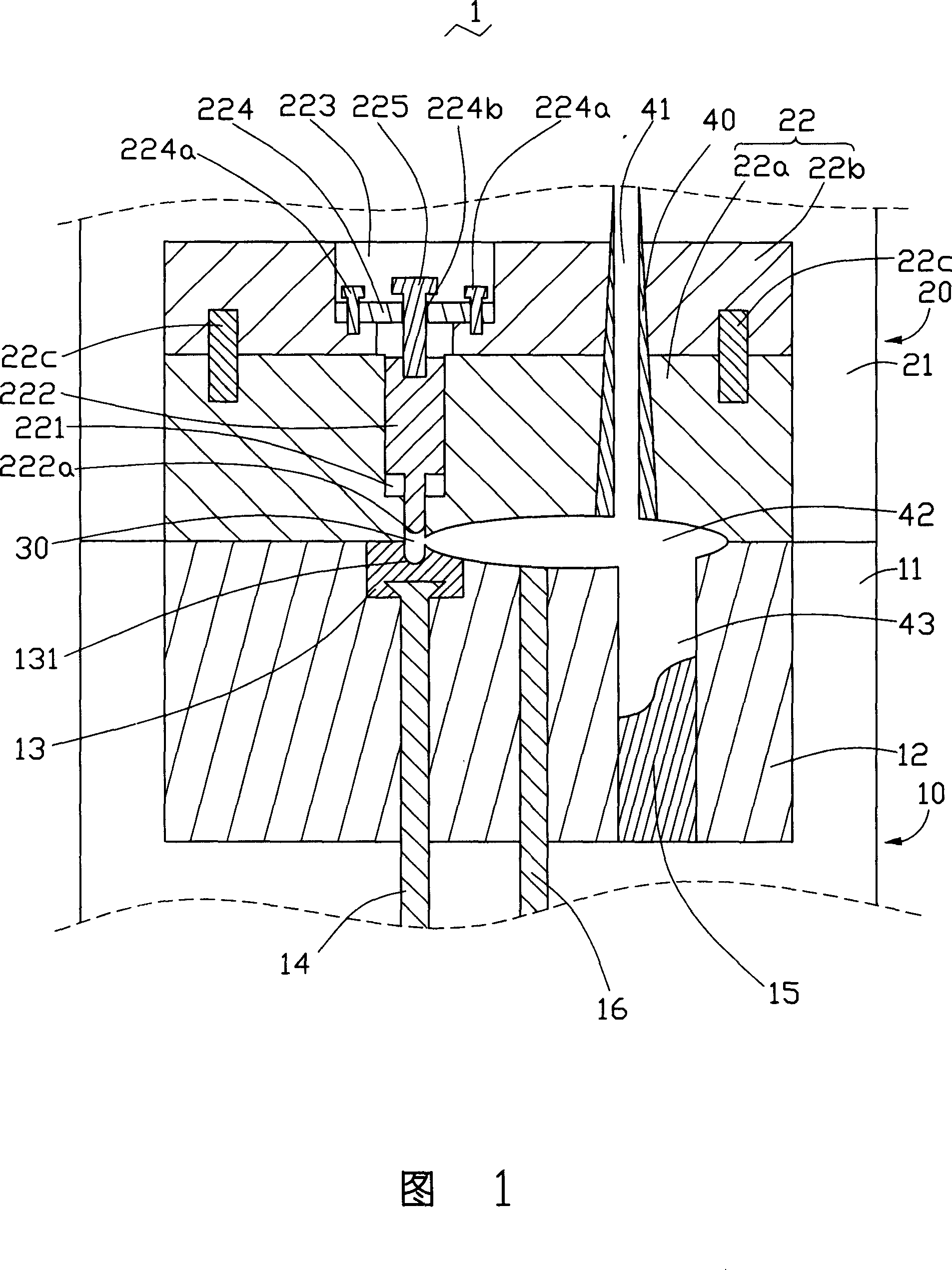
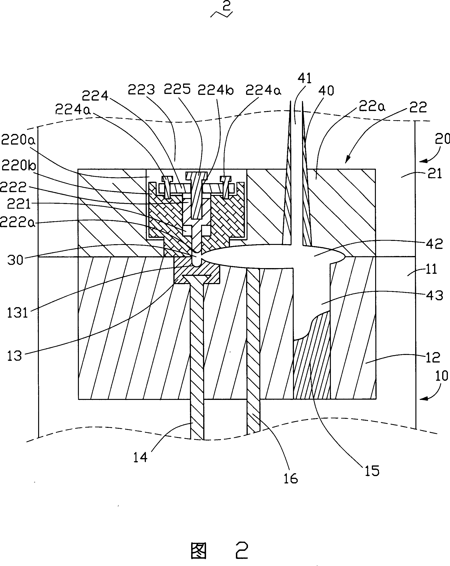
[0012] Referring to FIG. 1 , the optical element forming mold 1 provided by the first embodiment of the present invention includes a first parting mold 10 and a second parting mold 20 matched with the first parting mold 10 .

[0013] Wherein, the second split mold 20 includes a second mold base 21 and a second mold core 22 embedded in the second mold base 21 . The second mold core 22 includes a matched first module 22a and a second module 22b. The first module 22a includes a mold cavity 221 and an insert 222 embedded in the mold cavity 221, and the insert 222 has a molding surface 222a. The second module 22b includes an opening 223 , and the central axis of the mold cavity 221 coincides with the central axis of the opening 223 . The second module 22b further includes a fixing block 224 and an adjust...


PUM


Abstract

A mould for forming an optical element with adjustable thickness has the first mould core with the first moulding surface, and the second mould core cooperating with the first one and with a moulding cavity, an embedded part in said moulding cavity and having the second moulding surface, a fixed pad with a screwed through hole, and an adjusting screw in said screwed through hole and fixed to said embedded part.

Description

【Technical field】 [0001] The invention relates to a mold, in particular to an optical element forming mold. 【Background technique】 [0002] In recent years, with the development of multimedia, there is an increasing demand for optical components mounted on laptop computers, videophones, and mobile phones. This increase in demand requires further miniaturization and low cost of the optical components themselves. Optical components such as micro-lenses, light guide plates, etc., are usually molded by injection molding. The use of injection molding can greatly improve production efficiency and output, and reduce costs. [0003] The traditional optical element injection molding mold usually includes a first parting mold and a second parting mold that cooperate with each other. The first parting mold and the second parting mold respectively include a mold base and are embedded in the mold base and have a molding surface In the mold core, an insert with the molding surface can ...

Claims


Application Information

Patent Timeline
Patent Type & Authority Applications(China)
IPC IPC(8): B29C33/12B29C33/42B29C33/76B29C45/36B29C45/26B29C45/14B29L11/00
CPCB29C45/376B29L2011/0075
Inventor 江宗韦
Owner HONG FU JIN PRECISION IND (SHENZHEN) CO LTD
Why Eureka
Try Eureka