Scroll compressor

a compressor and scroll technology, applied in the direction of machines/engines, rotary/oscillating piston pump components, liquid fuel engines, etc., can solve the problems of reducing the thickness of the scroll lap, reducing the stroke volume, and reducing the strength, so as to reduce the leakage loss between the compression chambers, the effect of reducing the pressure deformation and effectively preventing galling or abnormal wear

Active Publication Date: 2006-06-01
PANASONIC CORP
View PDF3 Cites 11 Cited by
  • Summary
  • Abstract
  • Description
  • Claims
  • Application Information

AI Technical Summary

Benefits of technology

[0020] According to this aspect, since the value a / b exceeds 1.0, a compression chamber formed on the side of the inner wall of the scroll lap of the orbiting scroll is compressed faster than a compression chamber formed on the side of the outer wall of the scroll lap of the orbiting scroll, and leakage loss during compression process can be reduced. Since the value a / b is less than 1.5, thicknesses of both the scroll laps do become extremely thin and thus, the strength of the scroll lap can be secured.
[0022] According to this aspect, it is possible to optimally design the scroll compressor while taking into consideration a balance between the influence of a heat-reception loss in the suction process and a leakage loss between the compression chambers in the compression process.
[0024] According to this aspect, since the number of producing processes of the scroll lap working operation can be reduced, the leakage loss during the compression process can be reduced, and the producing cost can be reduced.
[0026] According to this aspect, the compression chamber formed on the side of the inner wall of the scroll lap of the orbiting scroll is compressed faster than the compression chamber formed on the side of the outer wall of the scroll lap of the orbiting scroll, leakage loss can be reduced, and the thickness of the scroll lap of the scroll can be changed. Thus, the strength of the scroll lap can be adjusted freely.
[0028] According to this aspect, the compression chamber formed on the side of the inner wall of the scroll lap of the orbiting scroll is compressed faster than the compression chamber formed on the side of the outer wall of the scroll lap of the orbiting scroll, and leakage loss during compression process can be reduced.
[0030] With this aspect, a pressure deformation is reduced, galling or abnormal wear can effectively be prevented, and the leakage loss between the compression chambers can effectively be reduced.

Problems solved by technology

However, in the case of the conventional structure in which both the scroll laps forming the fixed scroll and the orbiting scroll are formed of involute curves which are involutes of a circle having a constant radius, if a basic circle radius a, an involute angle (the number of windings) of the scroll, thickness t and height h of the scroll lap are determined, a degree of freedom with respect to the scroll shape is limited and a stroke volume and an incorporating volume ratio are determined uniquely and thus, the conventional structure has the following problems.
If the involute angle (the number of windings) is increased while keeping the outside shape size and the height of the scroll lap are set constant, there is a problem that the thickness of the scroll lap is reduced, the strength is deteriorated, or the stroke volume is reduced.
Thus, there is a problem that leakage loss between the compression chambers is generated during the compressing process.
However, since the lap is formed into the staircase shape, there is a problem that it is difficult to secure sealing properties between the laps of the staircase portions, the number of producing processes is increase, and cost thereof is increased.

Method used


Image

  • Scroll compressor
  • Scroll compressor
  • Scroll compressor

Examples


first embodiment

[0037] Embodiments of the present invention will be explained below with reference to the drawings. The invention is not limited by the embodiments.

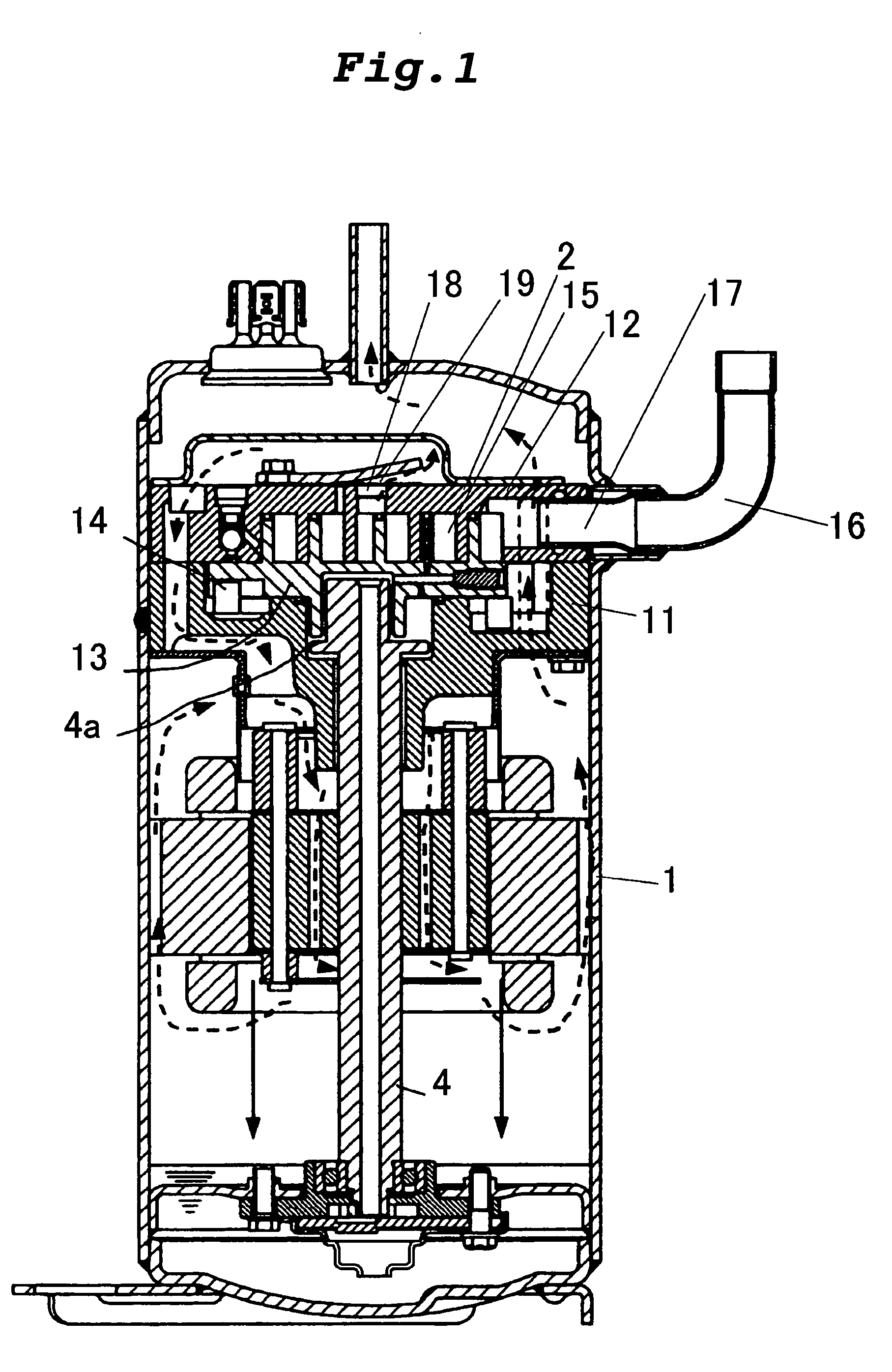
[0038]FIG. 1 is a sectional view of a scroll compressor of a first embodiment of the invention. An orbiting scroll 13 which meshes with a fixed scroll 12 is sandwiched between a main bearing member 11 of a crankshaft 4 which is fixed in a container 1 by means of welding or shrinkage fit and the fixed scroll 12 which is bolted to the main bearing member 11, thereby constituting a scroll compression mechanism 2. A rotation-restricting mechanism 14 such as an Oldham ring is provided between the orbiting scroll 13 and the main bearing member 11. The rotation-restricting mechanism 14 guides the orbiting scroll 13 such that rotation of the orbiting scroll 13 is prevented and is allowed to move in a circular orbit. The orbiting scroll 13 is eccentrically driven by a main shaft portion 4a on an upper end of the crankshaft 4, thereby allowing th...

second embodiment

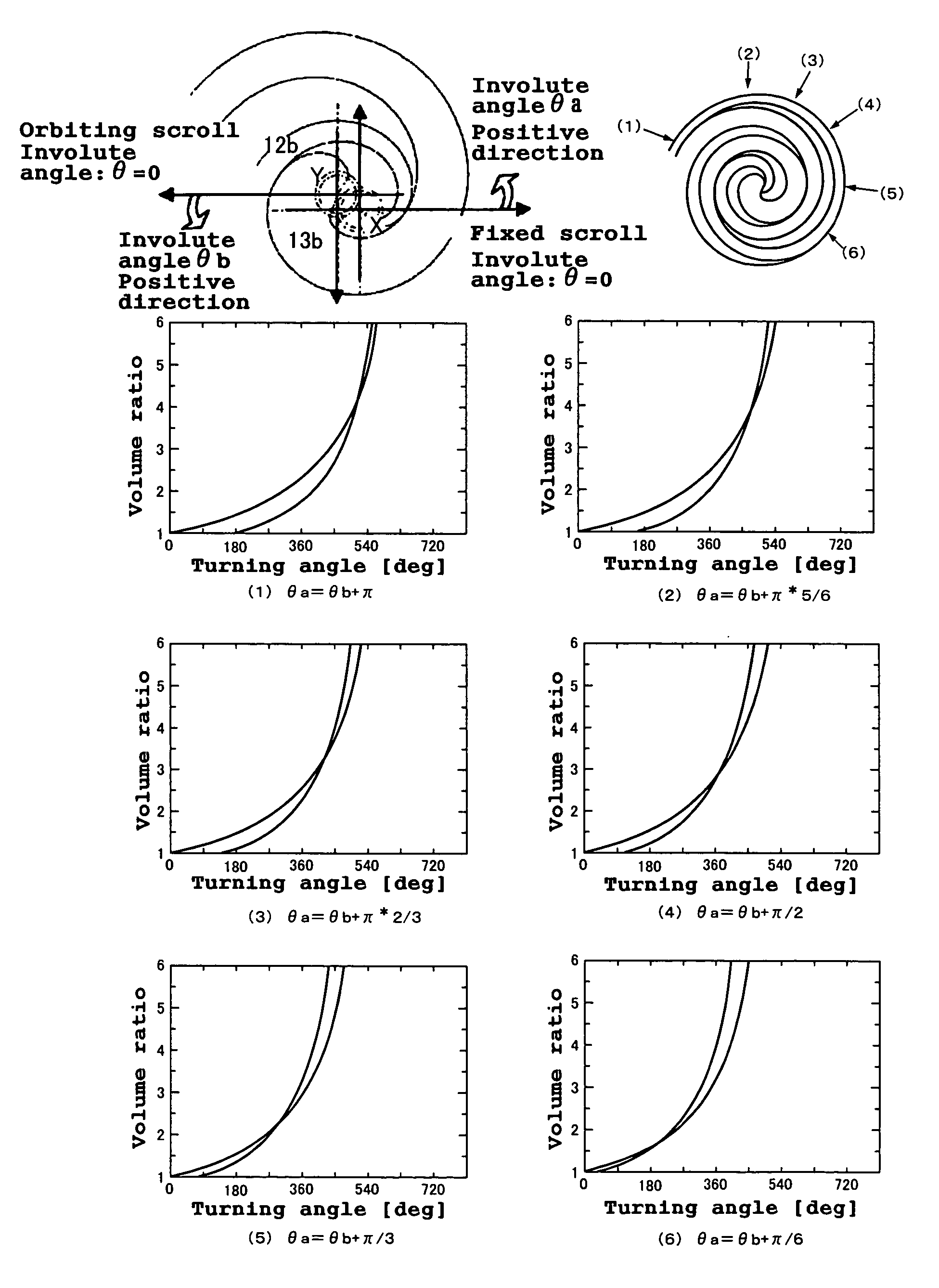
[0047]FIG. 4 are diagrams showing a volume variation of a compression chamber with respect to a turning angle when an involute angle θa of the scroll compressor of a second embodiment of the invention is varied in a range of θb15 with respect to a rotation angle (turning angle) of the crankshaft 4 when the involute angle θa at which the inner wall curve of the scroll lap 12b of the fixed scroll 12 is terminated, and an involute angle θb at which the inner wall curve of the scroll lap 13b of the orbiting scroll 13 is terminated are varied in the range of θb<θa<θb+π.

[0048] Here, a coordinate system X in which a basic circle center of the inner wall curve of the scroll lap 12b of the fixed scroll 12 is defined as an origin point is provided, and an arbitrary direction is defined as an involute angle: θ=0. A direction which is turned in the counterclockwise direction from the former direction is defined as a positive direction of the involute angle. Further, a coordinate system Y in wh...

third embodiment

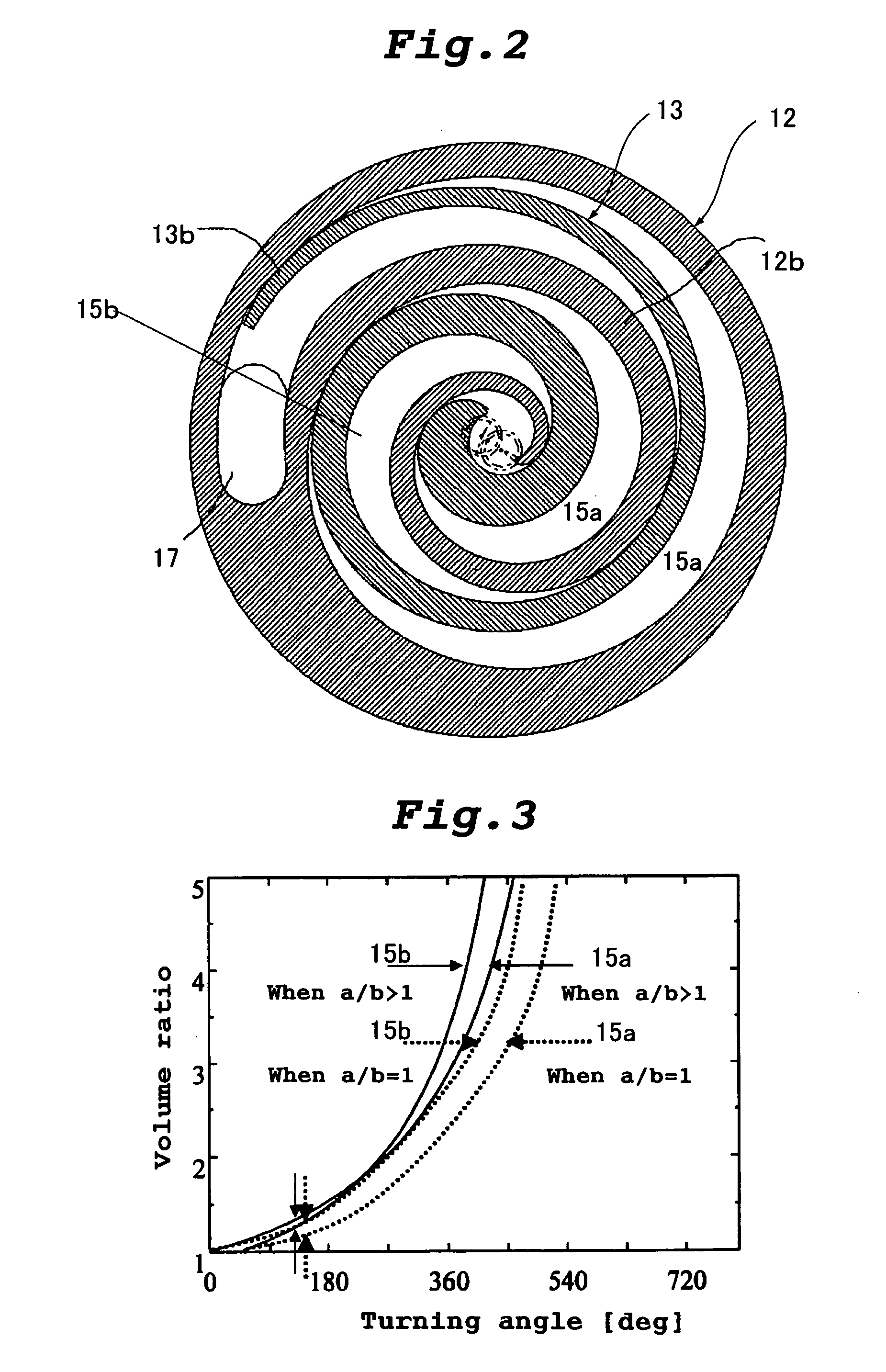
[0050]FIG. 5 are plan views showing a scroll lap shape of a scroll compressor of a third embodiment of the invention. In FIG. 5, the center position of the basic circle radius a and the center position of the basic circle radius b are separated from each other. With this, the compression chamber 15b formed on the side of the inner wall of the scroll lap 13b of the orbiting scroll 13 is compressed faster than the compression chamber 15a formed on the side of the outer wall of the scroll lap 13b of the orbiting scroll 13, and while keeping this characteristic, the thickness of the scroll lap can be varied. Therefore, the strength of the scroll lap can be adjusted freely.


PUM


Abstract

In a scroll compressor, an outer wall curve of a scroll lap of a fixed scroll and an inner wall curve of a scroll lap of an orbiting scroll are formed of involute curves whose basic circle radius is defined as “a”, an inner wall curve of the scroll lap of the fixed scroll and an outer wall curve of the scroll lap of the orbiting scroll are formed of involute curves whose basic circle radius is defined as “b”, and a value of a / b which is a ratio of the basic circle radius a and the basic circle radius b is set to a value exceeding 1.0 and less than 1.5. With this structure, a compression chamber formed on the side of the inner wall of the scroll lap of the orbiting scroll is compressed faster than a compression chamber formed on the side of the outer wall of the scroll lap of the orbiting scroll, and leakage loss during compression process can be reduced.

Description

TECHNICAL FIELD [0001] The present invention relates to a scroll compressor in which a fixed scroll and an orbiting scroll whose scroll laps rise from an end plate are meshed with each other to form a compression chamber therebetween, and when the orbiting scroll is turned along a circular orbit while restraining rotation by a rotation-restricting mechanism, the compression chamber moves while changing its volume, thereby carrying out suction, compression and discharge operations. BACKGROUND TECHNIQUE [0002] In conventional scroll compressors of this type, both scroll laps forming a fixed scroll and an orbiting scroll are formed of involute curves which are involutes of a circle having a constant radius in many cases. [0003] In some of scroll compressors, thicknesses of portions or entire scroll laps of the fixed scroll and orbiting scroll are varied from centers of the scrolls toward outer sides (see patent document 1 for example). [0004] In some of scroll compressors, a position o...

Claims


Application Information

Patent Timeline
Patent Type & Authority Applications(United States)
IPC IPC(8): F04C2/00F01C1/02F04C18/00F01C1/063F03C4/00F04C18/02F04C23/00F04C29/02F04C29/04
CPCF04C18/0215F04C18/0246F04C23/008F04C29/028F04C29/045F04C18/02
Inventor HIWATA, AKIRASAWAI, KIYOSHIMORIMOTO, TAKASHIFUTAGAMI, YOSHIYUKITSUJIMOTO, TSUTOMU
Owner PANASONIC CORP
Why Eureka
Try Eureka