Polishing apparatus and polishing method

a technology of polishing apparatus and polishing end point, which is applied in the field of polishing, can solve the problems of delay in signal transmission through interconnections, and difficulty in accurately monitoring a change in the thickness of hard mask film using these polishing end point detection techniques, and achieve the effect of accurately estimating the amount of polishing

Active Publication Date: 2009-04-30
KIOXIA CORP +1
View PDF5 Cites 12 Cited by
  • Summary
  • Abstract
  • Description
  • Claims
  • Application Information

AI Technical Summary

Benefits of technology

[0015]According to the present invention, the removal amount can be estimated accurately using the model equation. Therefore, polishing can be stopped at a desired time point.

Problems solved by technology

This is because a smaller distance between layered metal interconnects results in a larger line-to-line capacitance, which causes a delay in signal transmission through the interconnects.
Consequently, it is difficult to accurately monitor a change in thickness of the hard mask film using these polishing end point detection techniques.

Method used


Image

  • Polishing apparatus and polishing method
  • Polishing apparatus and polishing method
  • Polishing apparatus and polishing method

Examples


Embodiment Construction

[0023]Embodiments of the present invention will be described below with reference to the drawings.

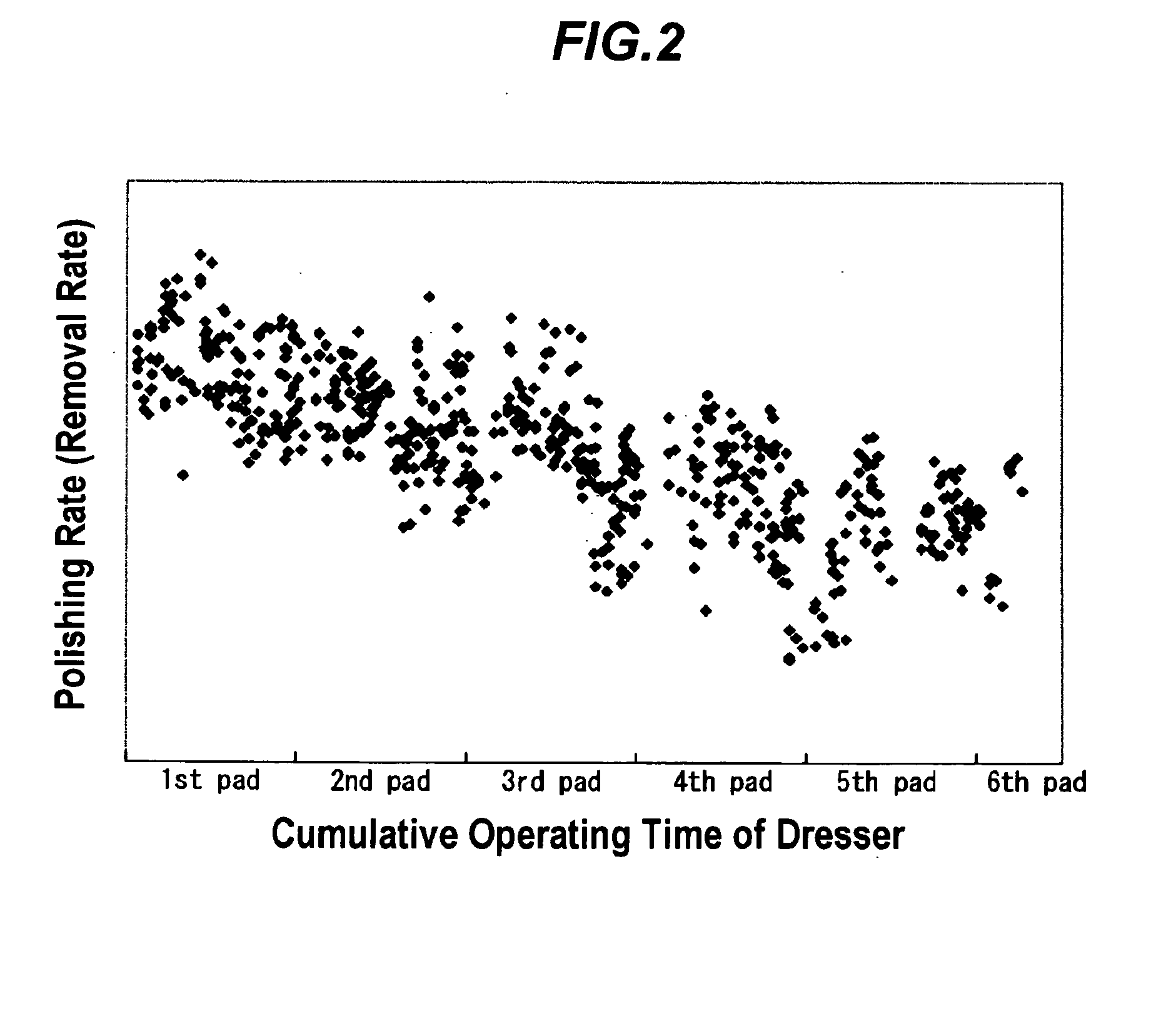
[0024]The inventors have studied effects of a cumulative operating time of a dresser (or a conditioner), which is to perform dressing (conditioning) of a polishing surface of a polishing pad, on a polishing rate (i.e., a removal rate). As a result, the inventors have discovered that there is a correlation between the cumulative operating time of the dresser and the polishing rate. FIG. 2 is a diagram showing data obtained from plural substrates polished. In FIG. 2, the data are plotted on a coordinate system having a vertical axis representing a polishing rate (removal rate) and a horizontal axis representing a cumulative operating time of a dresser. It can be seen from FIG. 2 that the polishing rate decreases as the cumulative operating time of the dresser increases.

[0025]In general, a dresser has a longer lifetime than a polishing pad. Therefore, it is normal that plural polishing pad...


PUM


Abstract

The present invention provides a apparatus for polishing an object material such as a film on a substrate. This apparatus includes a polishing table for holding a polishing pad having a polishing surface, a motor configured to drive the polishing table, a holding mechanism configured to hold a substrate having an object material to be polished and to press the substrate against the polishing surface, a dresser configured to dress the polishing surface, and a monitoring unit configured to monitor a removal amount of the object material. The monitoring unit is operable to calculate the removal amount of the object material using a model equation containing a variable representing an integrated value of a torque current of the motor when polishing the object material and a variable representing a cumulative operating time of the dresser.

Description

BACKGROUND OF THE INVENTION[0001]1. Field of the Invention[0002]The present invention relates to an apparatus and method for polishing an object material while estimating a removal amount of the object material using a model equation.[0003]2. Description of the Related Art[0004]An interlevel dielectric having a low dielectric constant is an essential technology for a high-density multi-level interconnect structure. This is because a smaller distance between layered metal interconnects results in a larger line-to-line capacitance, which causes a delay in signal transmission through the interconnects. Thus, there has recently been a trend to use a low-k material having a low dielectric constant as the interlevel dielectric. The low-k material has an advantage of having a low dielectric constant, but on the other hand the low-k material has low mechanical strength and is relatively easily removed from a substrate. Thus, in order to prevent removal of the low-k material, a hard mask fil...

Claims


Application Information

Patent Timeline
Patent Type & Authority Applications(United States)
IPC IPC(8): B24B49/00B24B49/16B24B7/20B24B37/013H01L21/304
CPCB24B49/16B24B37/013
Inventor NAKAO, HIDETAKAHAYASHI, EISAKUOISHI, KUNIOHAYAKAWA, ISAOMIYAKE, YOSHIAKITATEYAMA, YOSHIKUNIASHIHARA, TAKESHI
Owner KIOXIA CORP
Why Eureka
Try Eureka