Underwater noiseless, drag-reducing and antifouling bionic housing

An anti-fouling and shell technology, which is applied in the field of bionic shells and underwater bionic shells, can solve the problems of reducing ship speed, affecting human health, affecting ship waveguide dynamics, economy and safety, etc., to achieve improved anti-fouling Pollution ability and the effect of reducing radiated sound

Inactive Publication Date: 2017-05-31
NORTHWESTERN POLYTECHNICAL UNIV
View PDF5 Cites 12 Cited by
  • Summary
  • Abstract
  • Description
  • Claims
  • Application Information

AI Technical Summary

Problems solved by technology

Fouling organisms will adhere to the surface of the hull during the ocean voyage of the ship, increasing the load capacity of the hull and the friction of the ship, reducing the speed of the ship, aggravating the corrosion of the hull, and affecting the power, economy and safety of the ship's waveguide
In order to reduce the impact of marine fouling organisms on the hull structure caused by the attachment of the ship and the increase in resistance, the current solution is to apply a layer of toxic paint on the surface of the ship. The paint will slowly hydrolyze and release copper, mercury, Heavy metals such as tin and lead are used to poison the organisms in the ocean, but the release and deposition of these poisons destroy the ecological balance in the ocean and indirectly affect human health

Method used


Image

  • Underwater noiseless, drag-reducing and antifouling bionic housing
  • Underwater noiseless, drag-reducing and antifouling bionic housing
  • Underwater noiseless, drag-reducing and antifouling bionic housing

Examples


Embodiment 1

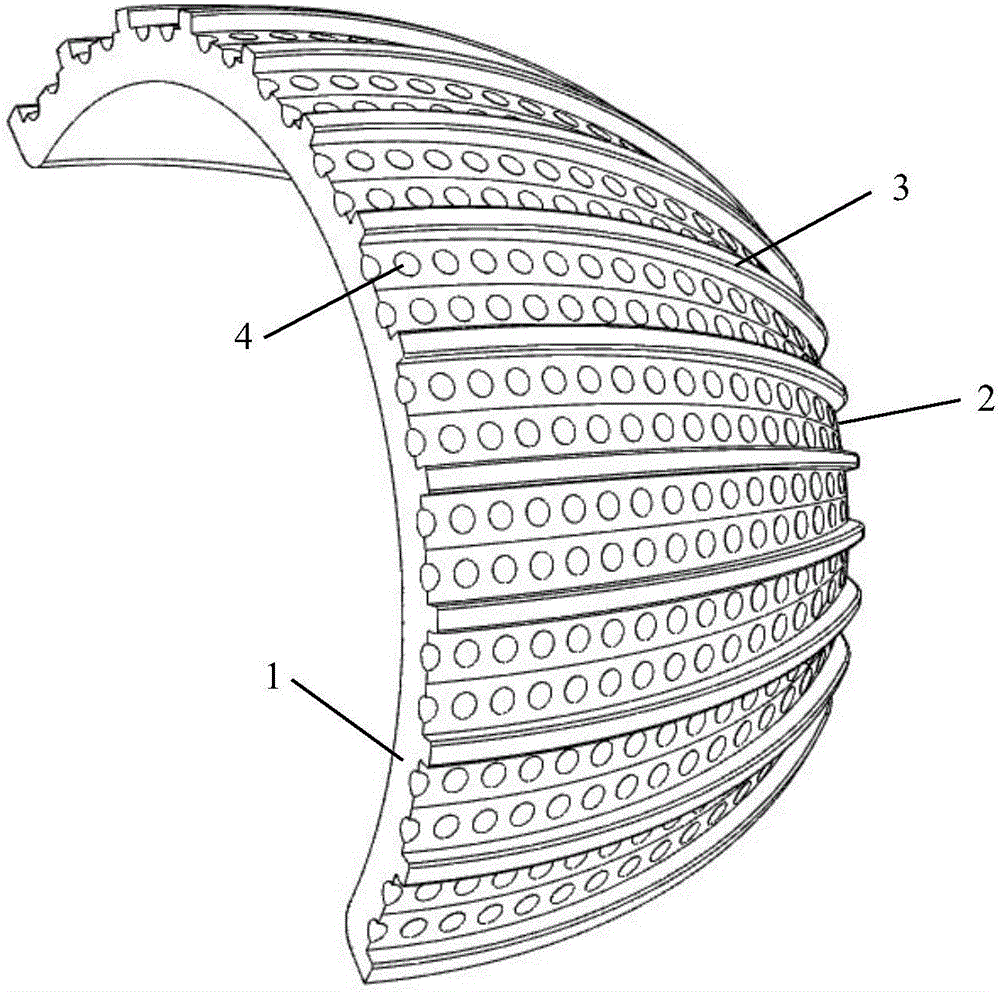
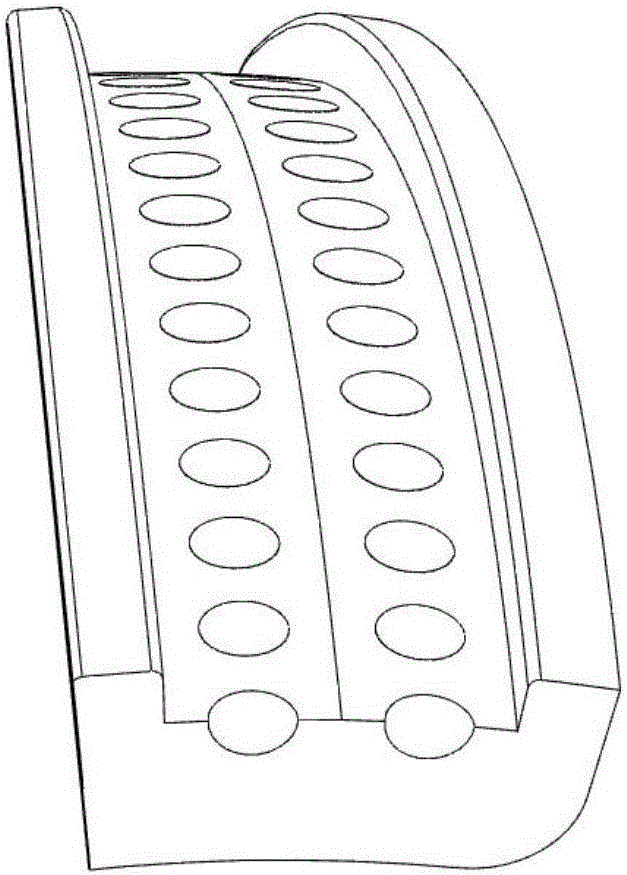
[0021] like figure 1 Shown is a schematic diagram of the radial U-shaped groove bionic shell of the present invention, figure 2 Shown is a partially enlarged schematic diagram of the U-shaped groove. Radial U-shaped grooves 2 are distributed on the outer surface of the substrate 1, and the radial U-shaped grooves 2 are formed by several micro-ridge structures 3 on the outer surface of the substrate 1, and there are regular lattice distributions on the surface of the substrate 1 in each groove 2. The spherical crown-shaped pit 4. The wall thickness of the U-shaped groove 2 is 4 mm, the height of the groove wall is 3 mm, and the maximum width of the U-shaped groove 2 is 15 mm. The diameter of the spherical crown-shaped pits 4 distributed on the outer surface of the substrate 1 in the U-shaped groove 2 is 4 mm, the pitch of the pits 4 is 8 mm, and the depth of the pits 4 accounts for 30% of the thickness of the substrate 1 .

Embodiment 2

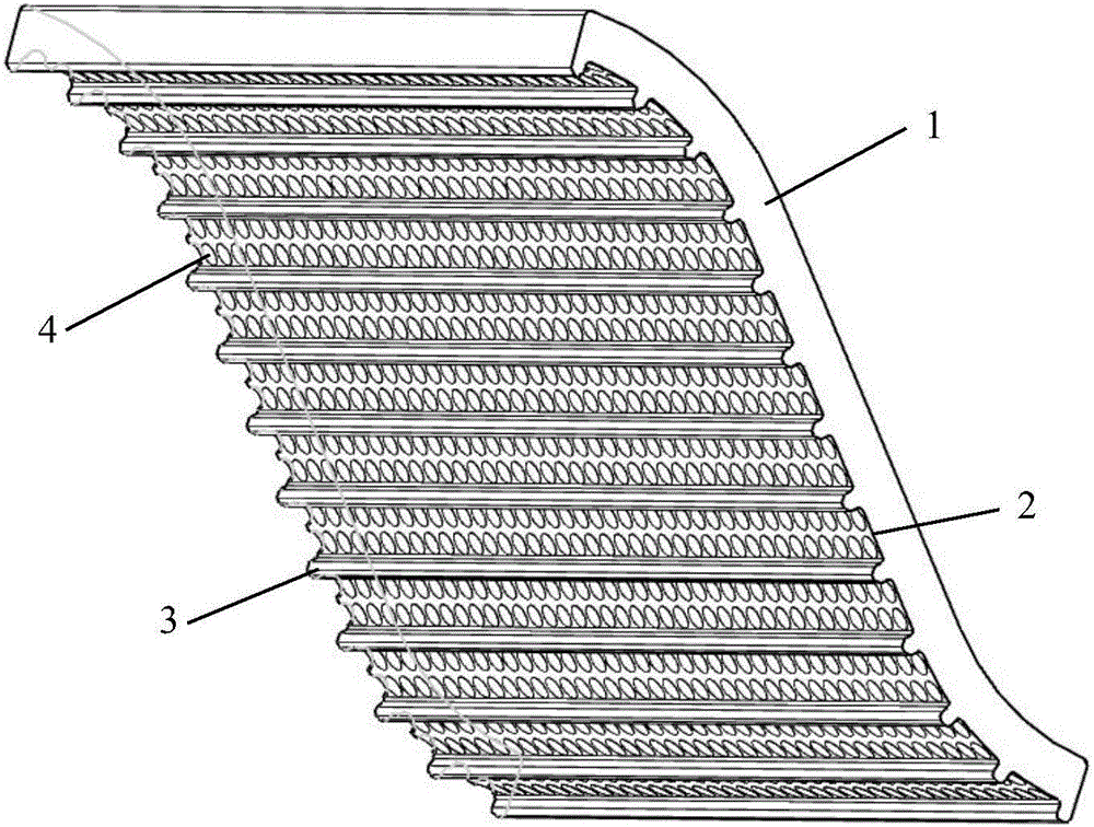
[0023] like image 3 Shown is a schematic diagram of the parallel U-shaped groove bionic shell of the present invention. Parallel U-shaped grooves 2 are distributed on the outer surface of the substrate 1. The parallel U-shaped grooves 2 are formed by several micro-ridge structures 3 on the outer surface of the substrate 1, and there are regular grooves on the outer surface of the substrate 1 in each groove 2. Spherical crown-shaped pits 4 distributed in a lattice. The wall thickness of the U-shaped groove 2 is 4mm, and the height of the groove wall is 3mm. The width of the U-shaped groove 2 is 1 cm. The spherical crown-shaped pits 4 distributed on the outer surface of the substrate 1 in the U-shaped groove 2 have a bottom circle diameter of 3 mm, a pitch of 6 mm between the pits 4, and a depth of the pits 4 accounting for 20% of the thickness of the substrate 1 .


PUM


Abstract

The invention relates to an underwater noiseless, drag-reducing and antifouling bionic housing, and belongs to the technical field of the ship building and ocean engineering. Parallel or radial U-shaped channels are distributed on the outer surface of a hard housing substrate. The U-shaped channels are formed by multiple strips of minitype ridge-shaped structures on the outer surface of the substrate. The outer surface of the substrate in each channel is provided with spherical-crown-shaped grooves distributed in the regular dot matrix. The underwater noiseless, drag-reducing and antifouling bionic housing is capable of, through the channel and groove design on the surface of the substrate, enabling the wave to be hindered in the transmission process of the housing, realizing the effective control of the vibration transmission, reducing the radiated sound, affecting the generation of the resistance through the effective control of the contact of the surface and the fluid, achieving the goal of the energy conservation and drag reduction, and improving the antifouling ability of the housing surface as the underwater creatures are easily fallen off because of the unstable attachment.

Description

technical field [0001] The invention belongs to the field of ships and marine engineering. The invention relates to a bionic shell, in particular to an underwater bionic shell with the characteristics of quietness, drag reduction and antifouling. Background technique [0002] Ships are complex large-scale power machinery structures, and their vibration and noise reduction technology has always been one of the focuses of engineering research. Excessive structural vibration and the noise caused by vibration will cause physical discomfort of the crew, reduce work efficiency, and even damage health. At the same time, if some precision equipment and instruments on the ship work in a strong vibration environment for a long time, the service life will be shortened, or even damaged and malfunction, which will affect the normal operation of the ship. In addition, the radiated noise generated by the hull can have adverse effects on marine life. While humans use the ocean, they shou...

Claims


Application Information

Patent Timeline
Patent Type & Authority Applications(China)
IPC IPC(8): B63B3/16
CPCB63B3/16
Inventor 盛美萍王敏庆马建刚秦琪
Owner NORTHWESTERN POLYTECHNICAL UNIV
Why Eureka
Try Eureka