electrical installation equipment

A technology for installing equipment and electrical installation, which is applied in the direction of electrical components, circuits, emergency protection devices, etc., and can solve problems such as high cost

Inactive Publication Date: 2012-02-22
ABB PATENT GMBH
View PDF0 Cites 3 Cited by
  • Summary
  • Abstract
  • Description
  • Claims
  • Application Information

AI Technical Summary

Problems solved by technology

[0007] The manufacture of special equipment, especially the casing, requires higher costs due to the need for special molds

Method used


Image

  • electrical installation equipment
  • electrical installation equipment
  • electrical installation equipment

Examples


Embodiment Construction

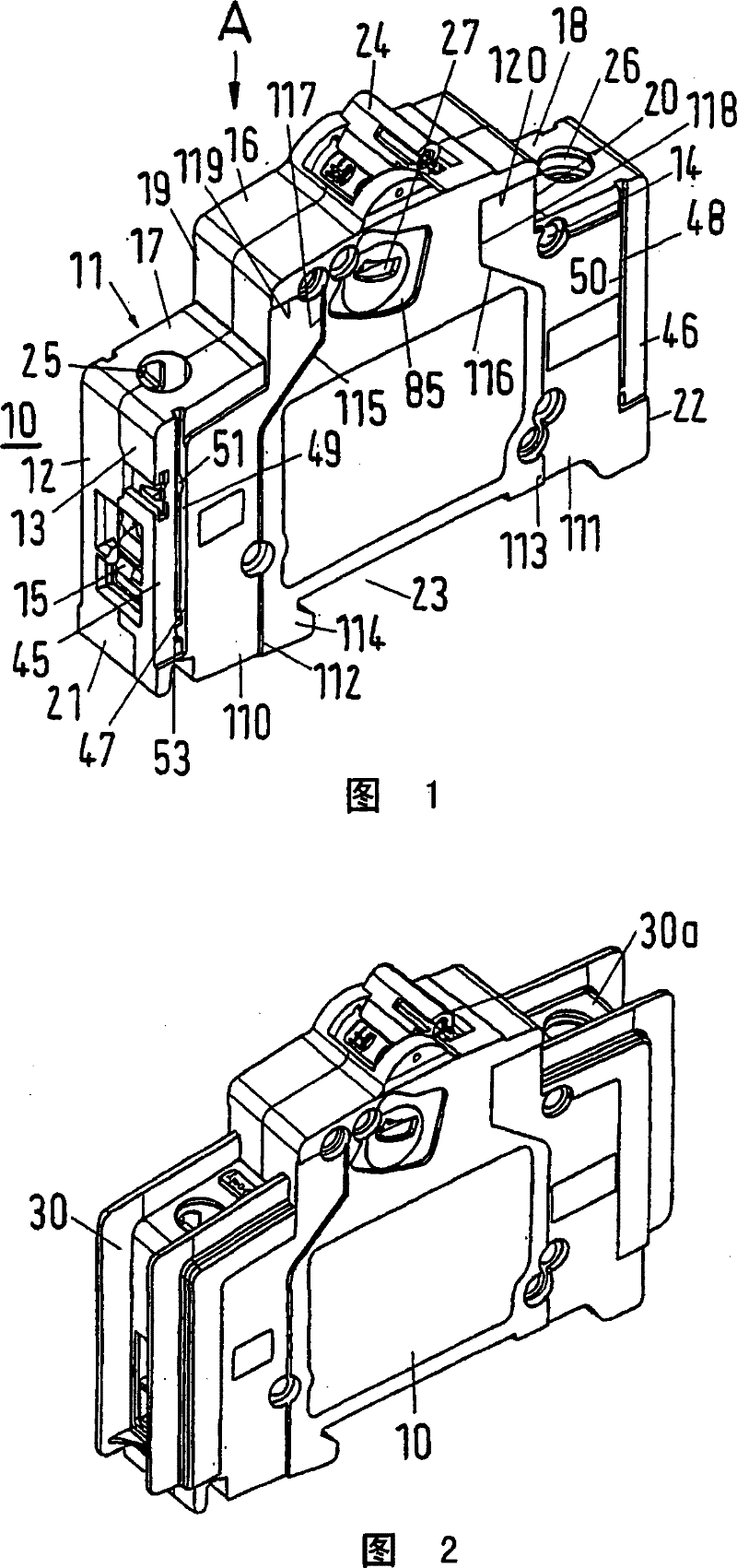
[0036] now refer to figure 1 . The circuit breaker 10 shown there is a single-pole circuit breaker, the outer contour of which corresponds to that of the circuit breaker S2 of ABB Stotz-Kontakt GmbH, Heidelberg. The circuit breaker has a housing 11 comprising two half-shells 12 and 13 which lie against one another and are connected to one another here by means of riveting points 14 , only one of which is marked here. Inside the housing 11 , there are conductive electrical components such as terminals 15 . This housing 11 is made with tube base structure, and it has a front face wall body 16, two back face wall bodies 17 and 18 and two front narrow side wall bodies 19, 20 and two back narrow side wall bodies 21, 22; the front narrow side walls 19, 20 connect the front front walls 16 and the rear front walls 17, 18 together, and then the rear narrow side walls 21 and 22 is connected to said rear frontal walls 17,18. In addition, the circuit breaker has a fastening wall 23 wi...


PUM


Abstract

The invention relates to an electrical installation device having a housing (11) in which electrically conductive components are arranged, said openings (27; 60, 61) being accessible through openings (27; member. At least one opening (27; 60, 61) can be assigned at least one wall-shaped insulating barrier made of electrically insulating material, by means of which the distance between two adjacent openings (27; 60, 61) can be increased. Air gaps and creepage distances, wherein the insulation barrier is fixable on the housing (11) of the installation device.

Description

technical field [0001] The invention relates to an electrical installation device. Background technique [0002] Electrical installation devices, such as circuit breakers, have a housing in which components belonging to the installation device, such as terminals, are accommodated, which are made of electrically conductive material and are live under voltage during operation. The housing has openings through which components under electrical voltage can be accessed. For example, two openings are assigned to each terminal: through one of the openings the screw of the terminal is actuated, and through the other opening the electrical conductor to be connected is introduced. [0003] If a plurality of circuit breakers are joined together, for example, to form a single unit, further openings are provided in the opposite wide side walls, through which openings a connecting piece is inserted, which connects the two switching units. Parts belonging to each other, such as movable e...

Claims


Application Information

Patent Timeline
Patent Type & Authority Patents(China)
IPC IPC(8): H01H71/02
CPCH01H71/0271
Inventor A·奥尔班R·科默特M·比特茨
Owner ABB PATENT GMBH
Why Eureka
Try Eureka