Electromagnetic relay structure

A technology of electromagnetic relay and magnetic circuit, applied in the direction of electromagnetic relay, detailed information of electromagnetic relay, relay, etc., can solve the problems that it is difficult to improve the consistency and efficiency of parts, affect the performance of electromagnetic relay, and the structure of moving spring is not stable, etc., to achieve Compact structure, improved air gap and creepage distance, and reduced product volume

Pending Publication Date: 2020-10-16
XIAN HONGFA ELECTRIC APPLIANCE
View PDF0 Cites 0 Cited by
  • Summary
  • Abstract
  • Description
  • Claims
  • Application Information

AI Technical Summary

Problems solved by technology

In the traditional electromagnetic relay structure, the pins of PCB pins, static lead terminals and moving lead terminals are designed on one side of the base. Due to the complex structure of the pins, especially the pins of the moving lead terminals will be bent at 90 degrees and The bending distance is greater than 3mm, and then riveted with the moving spring. After riveting, the structure of the moving spring is not stable, and the pressure fluctuates. It is difficult to improve the consistency and efficiency of the parts; Due to structural reasons, the pressure is not very stable, and the pressure difference before and after insertion is very large, which makes it difficult to improve efficiency. At the same time, the static and dynamic terminals need to be fixed on the upper limit of the base, so they need to be riveted first, followed by high-temperature glue If it is fixed, the corresponding parameters will also change during the process, which will affect the performance of the electromagnetic relay.

Method used


Image

  • Electromagnetic relay structure
  • Electromagnetic relay structure
  • Electromagnetic relay structure

Examples


Embodiment Construction

[0033] The present invention will be described in further detail below in conjunction with the accompanying drawings, which are explanations rather than limitations of the present invention.

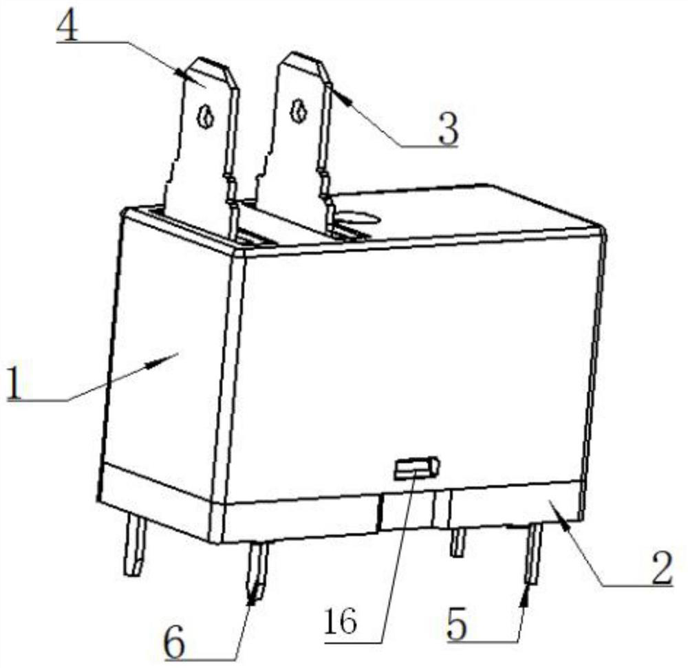
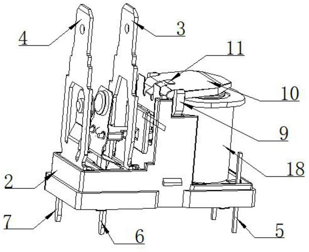
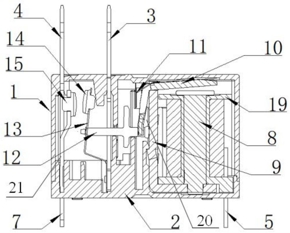
[0034] see figure 1 , figure 2 and image 3 , an electromagnetic relay structure, including a magnetic circuit mechanism and a contact element arranged in a casing 1;

[0035] The magnetic circuit mechanism includes a bobbin 19 arranged on the base 2, the bobbin 19 is longitudinally provided with a first through-slot through the bobbin 19, the first through-slot is provided with an iron core 8, and the bobbin 19 is wound There is a coil 18, and the coil 18 is connected to the terminal 5 of the coil 18 that runs through the base 2; the base 2 is longitudinally provided with a mounting slot 20 for installing the L-shaped yoke 9 and the armature 10; the armature 10 includes a longitudinally inclined section and is connected to it The oblique section, the vertical oblique section is embe...


PUM


Abstract

The invention discloses an electromagnetic relay structure which comprises a magnetic circuit mechanism and a contact element. The magnetic circuit mechanism comprises a coil rack, an iron core is arranged in the coil rack, a coil is wound on the coil rack, and the coil is connected with a coil leading-out terminal; a mounting groove for mounting a L-shaped yoke and an armature is longitudinally formed in the base; the armature comprises a longitudinal inclined section and a transverse inclined section connected with the longitudinal inclined section, the longitudinal inclined section is embedded in the mounting groove, and the end part of the longitudinal inclined section is connected with a push rod for pushing a movable contact spring; the transverse inclined section is positioned abovethe iron core through a pressure spring, the knife edge surface of the L-shaped yoke is in fit contact with the connecting rotating shaft of the transverse inclined section and the longitudinal inclined section of the armature, and the transverse section of the L-shaped yoke is fixed with the coil rack and the iron core through riveting; the contact element comprises a static lead terminal and amoving lead terminal, the head of the static lead terminal and the head of the moving lead terminal both penetrate out of the shell, and a first PCB pin and a second PCB pin are arranged at the bottomof the shell. The electromagnetic relay structure has the advantages of ingenious design, simple assembly, reduced cost and improved high-voltage resistance and insulation performance of the product.

Description

technical field [0001] The invention belongs to the technical field of electromagnetic relays and relates to an electromagnetic relay structure. Background technique [0002] Electromagnetic relay is an electric control device, which is widely used in household appliances, remote control, communication and automation control circuits. Its essential function is to control the large current of the output circuit through the small current of the input circuit. In the traditional electromagnetic relay structure, the pins of PCB pins, static lead terminals and moving lead terminals are designed on one side of the base. Due to the complex structure of the pins, especially the pins of the moving lead terminals will be bent at 90 degrees and The bending distance is greater than 3mm, and then riveted with the moving spring. After riveting, the structure of the moving spring is not stable, and the pressure fluctuates. It is difficult to improve the consistency and efficiency of the pa...

Claims


Application Information

Patent Timeline
Patent Type & Authority Applications(China)
IPC IPC(8): H01H50/04H01H50/44H01H50/58H01H50/14
CPCH01H50/041H01H50/14H01H50/443H01H50/58H01H2050/446
Inventor 仇敏王建奇刘欣
Owner XIAN HONGFA ELECTRIC APPLIANCE
Why Eureka
Try Eureka