Improved cloth dyeing machine structure

A cloth dyeing machine and pipeline technology, which is applied in the direction of liquid/gas/steam jetting to propel fabrics, etc., can solve the problems of increased power consumption and fan power output, and achieve weight reduction, power output, power consumption, and thrust Reduced effect

Active Publication Date: 2015-08-19
FONGS NAT ENG (GUANGDONG) CO LTD
View PDF8 Cites 0 Cited by
  • Summary
  • Abstract
  • Description
  • Claims
  • Application Information

AI Technical Summary

Problems solved by technology

Increasing the air volume can increase the driving force, but the increase in the air

Method used


Image

  • Improved cloth dyeing machine structure
  • Improved cloth dyeing machine structure
  • Improved cloth dyeing machine structure

Examples


Embodiment Construction

[0025] The following is a non-limiting description of the device described in the application of the present invention through the accompanying drawings and examples, in order to make the public better understand the technical solution.

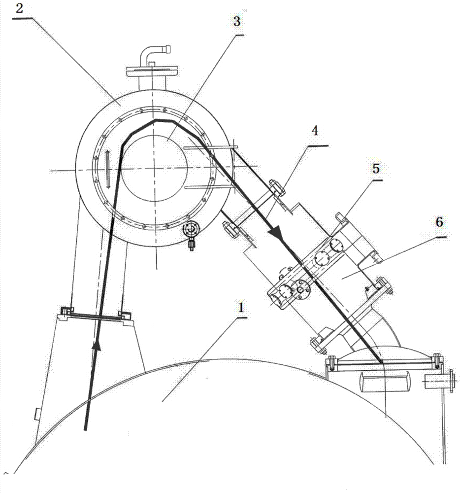
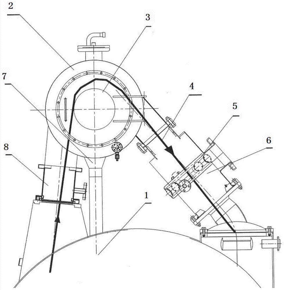
[0026] figure 1 It is a schematic diagram of the top structure of the dyeing machine in the prior art, including a main cylinder 1, and the top of the main cylinder 1 is provided with a front pipeline (left side in the figure), a cylinder head 2 and a rear pipeline (right side in the figure), which are connected in sequence, and the cylinder head 2 is provided with a drum 3, and the fabric 4 is driven by the drum to pass through the front pipeline, the cylinder head 2 and the rear pipeline in sequence, and the rear pipeline is provided with an atomized water nozzle 5 and a main wind nozzle 6 in sequence; figure 2 , the structure of the improved cloth dyeing machine described in the application of the present invention includes the main cylin...


PUM


Abstract

The application of the invention provides an improved cloth dyeing machine structure comprising a main cylinder. A front pipeline, a cylinder head and a rear pipeline are arranged at the top the main cylinder, wherein the front pipeline, the cylinder head and the rear pipeline are successively connected. A roller is arranged in the cylinder head; and a fabric unit driven by the roller passes through the front pipeline, the cylinder head and the rear pipeline successively. An atomized water nozzle and a wind main nozzle are successively arranged at the rear pipeline; and a front nozzle is also arranged at the front pipeline. When the front nozzles carries out spraying upwardly, an extra push force is provided for pushing the fabric unit to move. Most importantly, before entering the wind main nozzle, the fabric unit has been wetted to a certain extent by the front adjustable nozzle and the extra accumulated water is drained before entrance to the wind main nozzle, so that the water in the fabric unit is reduced and thus the weight is also reduced. Because of the extra push force of the front adjustable nozzle and the reduced weight of the fabric unit, the air load is also reduced, thereby reducing the power output and power consumption of the fan. On the basis of improvement, water nozzles can be arranged at the rear and in the front of the machine and free and flexible adjustment can be realized for operation according to the process requirement.

Description

technical field [0001] The application of the present invention relates to an improved structure of a cloth dyeing machine, especially an improvement to the structure of a cylinder top of a cloth dyeing machine, which belongs to the technical field of printing and dyeing equipment. Background technique [0002] Such as figure 1 Shown is the structure above the existing dyeing machine, the upper inverted V-shaped device is a whole connected by the nozzle, the cylinder head 2 and the cylinder 3, and is installed on the top of the main cylinder 1. The fabric 4 enters from the main cylinder 1 through the front pipe (the left side of the diagram), and is lifted up by the force of the wind, bypasses the drum 3 at the highest point, and then walks down, passing through the main wind nozzle 6 and the rear atomized water The nozzle 5 returns to the main cylinder 1 (the right side of the figure) through the rear pipeline. From the point of view of the illustration, the fabric 4 circ...

Claims


Application Information

Patent Timeline
IPC IPC(8): D06B3/28
Inventor 徐达明
Owner FONGS NAT ENG (GUANGDONG) CO LTD
Why Eureka
Try Eureka