Automatic sole cleaning machine

A sole cleaning and automatic technology, applied in the direction of cleaning boots and shoes, cleaning equipment, household cleaning devices, etc., can solve problems such as trouble

Inactive Publication Date: 2007-08-08
张宪宗
View PDF0 Cites 2 Cited by
  • Summary
  • Abstract
  • Description
  • Claims
  • Application Information

AI Technical Summary

Problems solved by technology

[0002] At present, in public places such as hotels, hospitals, restaurants, the structure of the sole cleaning machine for people to clean the soles is that a water tank is provided at the bottom of the box, a partition is arranged on the top of the water tank, a bracket is provided on the partition, and a load-bearing water spray is provided on the top of the bracket. The tank and the water spray ta

Method used


Image

  • Automatic sole cleaning machine

Examples


Embodiment Construction

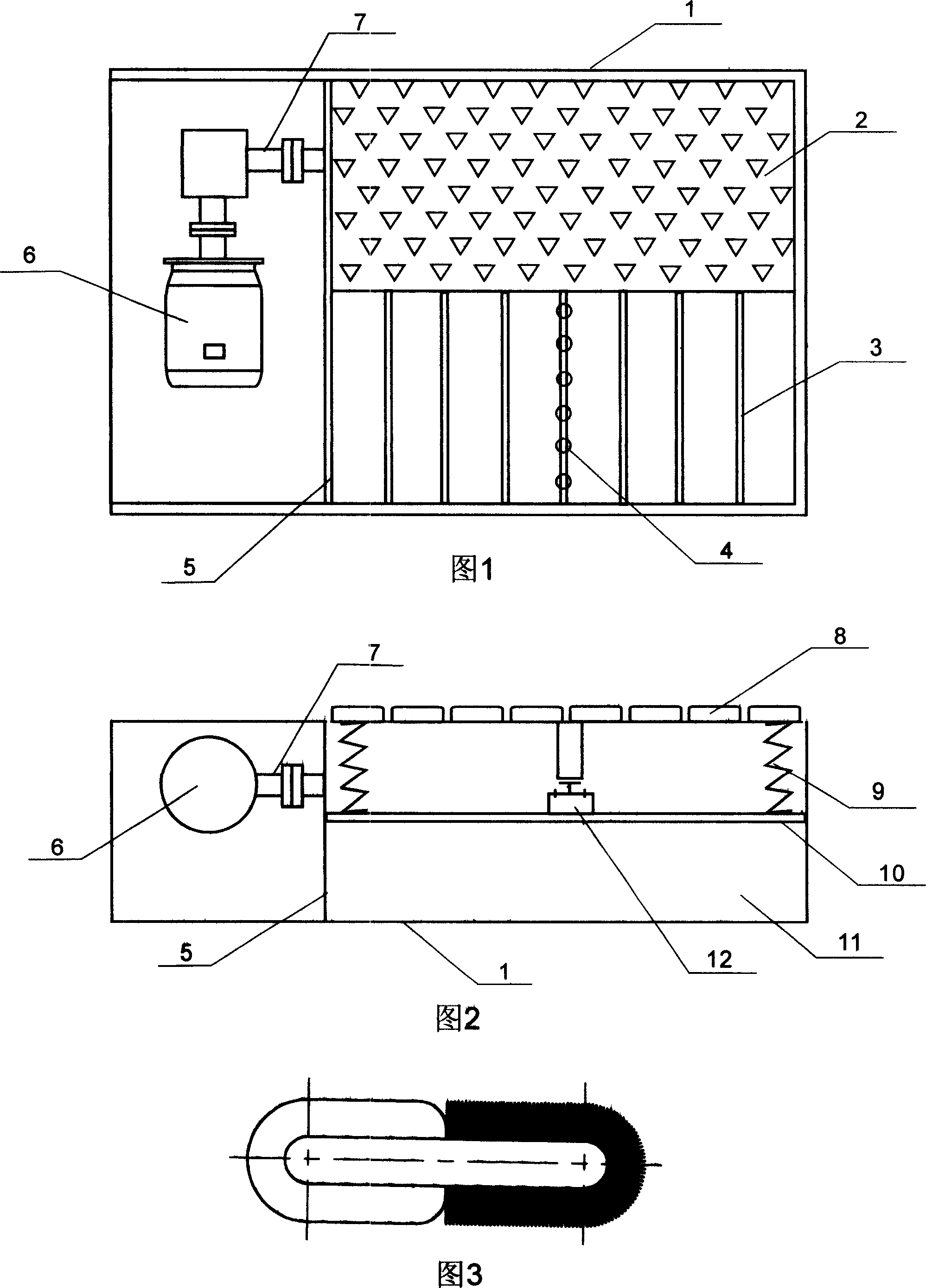
[0011] In Fig. 1, a partition 5 and an interlayer 10 are arranged in the inner cavity of the box body 1, and the box body 1 is divided into three independent spaces, and a motor 6 and a rotating shaft 7 are housed in one space, and the rotating shaft 7 extends through the partition plate 5. The upper layer of the other half is connected to the conveyor belt 4, and the conveyor belt 4 is connected to the cleaning brush 2 and the wiping cloth 8, and the cleaning brush 2 and the wiping cloth 8 are placed flat on the vertical frame 3, and the four corners above the interlayer 10 below the vertical frame 3 are equipped with springs 9. A switch 12 is installed at the center of the interlayer 10, and a water tank 11 is located below the interlayer 10.

[0012] During use, when the user steps on the cleaning brush 2 and the wiping cloth 8, the cleaning brush 2, the wiping cloth 8 and the vertical frame 3 will be pressed down at the same time. At this time, the spring 9 under the vertic...


PUM


Abstract

The invention relates to an automatic sole cleaning machine, wherein, the chamber of box is arranged with a baffle plate to divide it into two parts, while one part is arranged with a motor with a rotation axle inserted into another part via the baffle plate, and another part is arranged with a baffle layer to divide it into upper and lower layers, while the lower layer is water tank and the center of upper baffle plate is arranged with a start switch, and four angles of baffle layer are arranged with springs. The springs support the upright frame arranged with cleaning brush and wiper whose lower centers are arranged with transmission band connected with the rotation axle of motor to operate. The invention arranged switch, springs, upright frame, cleaning brush and wiper on the baffle plate at the upper layer of water tank, therefore, user only needs to arrange foot on the cleaning brush and wiper, to compress the upright frame to trigger the switch, and the motor will automatically start, with simple structure.

Description

technical field [0001] The invention relates to a shoe sole cleaning device, in particular to an automatic shoe sole cleaning machine which is automatically started and operated for cleaning. Background technique [0002] At present, in public places such as hotels, hospitals, restaurants, the structure of the sole cleaning machine for people to clean the soles is that a water tank is provided at the bottom of the box, a partition is arranged on the top of the water tank, a bracket is provided on the partition, and a load-bearing water spray is provided on the top of the bracket. The tank and the water spray tank are cleaned with a water pump spray cleaning brush. For such a shoe sole cleaning machine, people first need to start the switch by themselves, and the water spray head will spray the water and scatter it on the user's shoes and trousers. What is more troublesome is After the cleaning of the soles, it is necessary to find a wiping cloth to dry the vamp, which brings...

Claims


Application Information

Patent Timeline
IPC IPC(8): A47L23/22
Inventor 张宪宗
Owner 张宪宗
Why Eureka
Try Eureka