Lifting device

A lifting device and lifting rod technology, applied in the direction of lifting device, lifting frame, medical science, etc., can solve the problems of complex control, large structure consumption, etc., and achieve the effect of saving construction space

Active Publication Date: 2007-08-08
SIEMENS HEALTHCARE GMBH
View PDF1 Cites 18 Cited by
  • Summary
  • Abstract
  • Description
  • Claims
  • Application Information

AI Technical Summary

Problems solved by technology

In other words, the known solutions are structurally complex and require an overly complex control

Method used


Image

  • Lifting device
  • Lifting device
  • Lifting device

Examples


Embodiment Construction

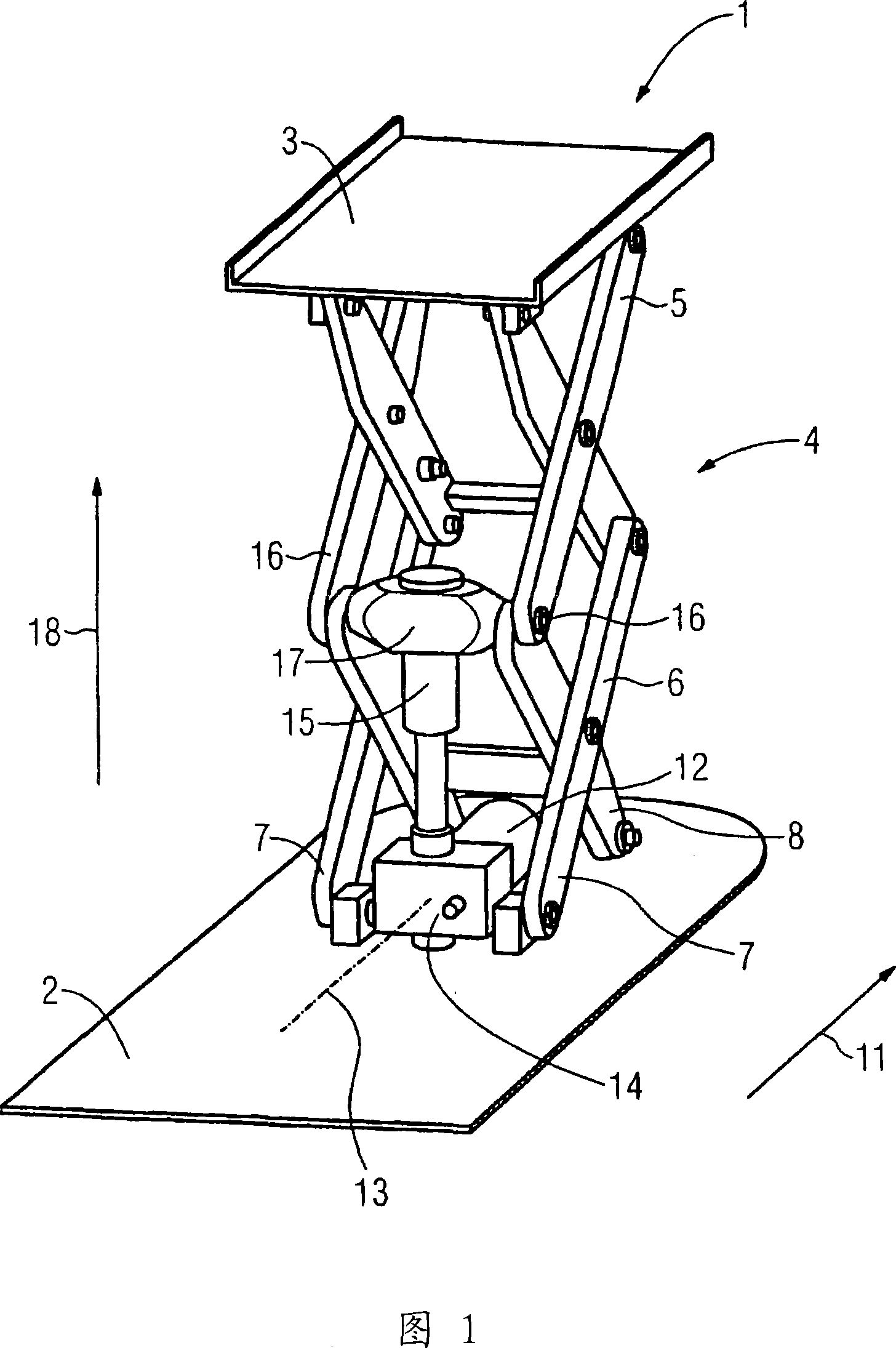
[0017] The lifting device 1 according to the invention essentially consists of a bottom in the form of a floor 2 , a top in the form of a hospital bed 3 and a lifting rod (see FIG. 1 ). Here, the lifting rod is made as a double-scissor-type mechanism or double-scissors 4 . In other words, it comprises two sets of scissors 5, 6 as struts, which are connected to each other by hinges.

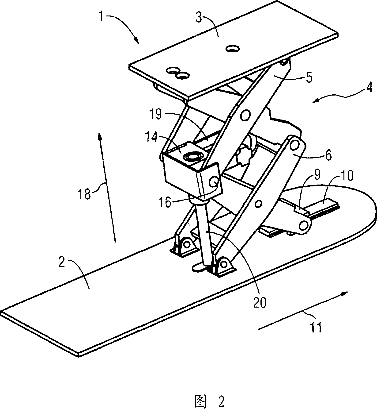
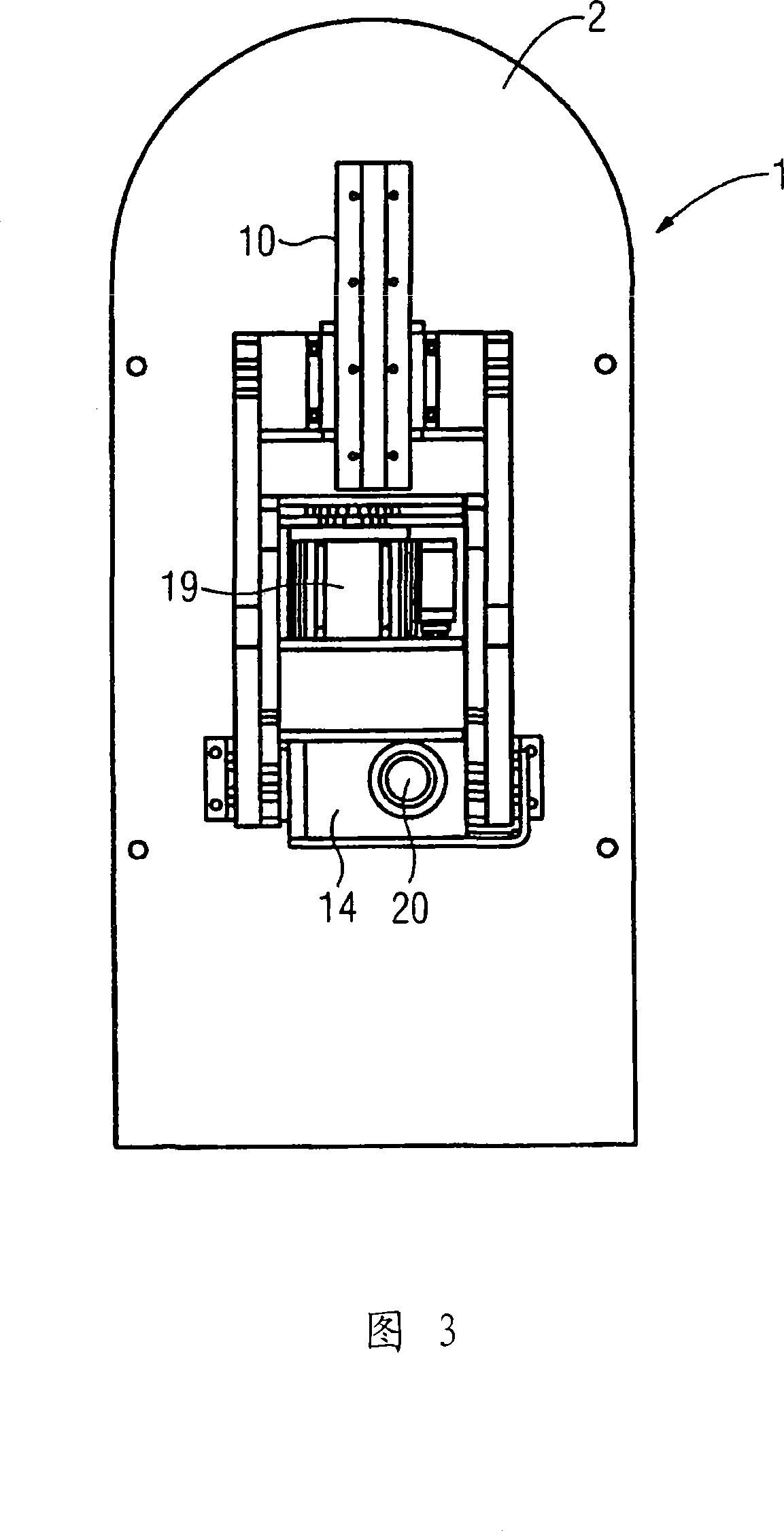
[0018] The lower scissors group 6 is connected to the base plate 2 with its front scissors feet 7 by hinges. The rear scissors feet 8 of the scissors group 6 are connected to each other by a slide block 9. When opening or closing the double scissors structure 4, the slide block slides back and forth along the sliding direction 11 on the slide rail 10 fixed on the base plate 2 (see FIG. 2 ).

[0019] Between the front and rear scissors feet 7, 8 of the lower scissors group 6, a motor 12 placed horizontally is fixed on the base plate 2. A hand crank (not shown) for emergency operation of the lifti...


PUM


Abstract

The invention relates to a lifting device (1) comprising a top part (3), a bottom part (2), a lifting rod assembly (4) that connects the top part (3) to the bottom part (2) and is provided with at least two partial rod assemblies (5, 6) which are interconnected via a central joint (16), and a drive unit (12, 14, 15, 19) for adjusting the height of the top part (3). In order to create a particularly simple lifting device, the drive unit (12, 14, 15, 19) grips the central joint (16).

Description

technical field [0001] The invention relates to a lifting device with a top and a bottom, comprising a lifting rod connecting the top and the bottom and a drive unit for adjusting the height of the top, the lifting rod has at least two struts connected by an intermediate hinge joint. Background technique [0002] Such lifting devices are known from the prior art. For example WO98 / 46137 shows such a lifting device for adjusting the height of a hospital bed. Among them, the lifting rod uses a parallelogram structure. A disadvantage of the known construction is that it requires a relatively large installation space. Furthermore, particularly large but not constant forces are required for the height adjustment. During height adjustment, different working speeds also occur. In other words, the known solutions are structurally complex and require an overly complex control. Contents of the invention [0003] In view of this situation, the technical problem to be solved by th...

Claims


Application Information

Patent Timeline
Patent Type & Authority Applications(China)
IPC IPC(8): B66F7/06A61G7/012
CPCB66F7/0666
Inventor 保罗·韦德纳康拉德·皮格
Owner SIEMENS HEALTHCARE GMBH
Why Eureka
Try Eureka