Precision micrometric displacement actuator used under polar region low-temperature environment

A low-temperature environment, micro-displacement technology, used in instruments, installations, optics, etc., to prevent wind and snow erosion, prevent erosion, and have good sealing effects

Active Publication Date: 2014-09-17
HARBIN INST OF TECH
View PDF5 Cites 5 Cited by
  • Summary
  • Abstract
  • Description
  • Claims
  • Application Information

AI Technical Summary

Problems solved by technology

At present, there is no such product in the world

Method used


Image

  • Precision micrometric displacement actuator used under polar region low-temperature environment
  • Precision micrometric displacement actuator used under polar region low-temperature environment
  • Precision micrometric displacement actuator used under polar region low-temperature environment

Examples


specific Embodiment approach 1

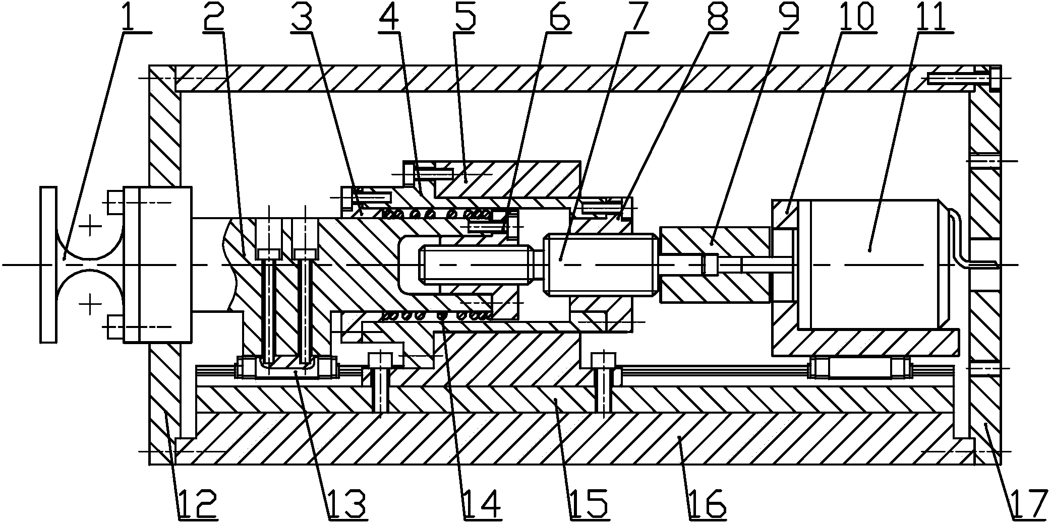
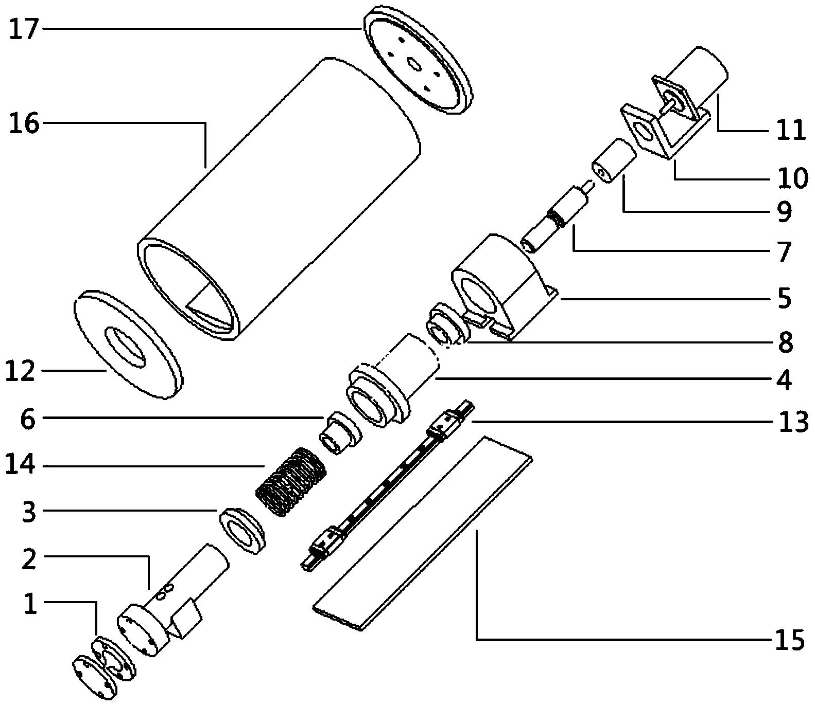
[0017] Specific implementation mode one: combine Figure 1-Figure 2 This embodiment is described. A precision micro-displacement actuator used in a polar low-temperature environment in this embodiment includes a drive mechanism, a differential screw mechanism, and a motion support mechanism. The differential screw mechanism and the drive mechanism are arranged in the motion support mechanism. The motion support mechanism includes a flexible shaft 1, a left end cover 12, a rolling linear guide 13, a backing plate 15, a housing 16 and a right end cover 17, the backing plate 15 is installed in the housing 16, and the rolling linear guide 13 is installed on the backing plate 15 Above, the left end cover 12 and the right end cover 17 are installed on the two ends of the housing 16 respectively, the flexible shaft 1 is installed on the left end of the drive rod 2, and the left end of the drive rod 2 passes through the left end cover 12 and fits with the gap between the left end cover...

specific Embodiment approach 2

[0024] Specific implementation mode two: combination Figure 1-Figure 2 The present embodiment will be described. The case 16 of the present embodiment is a cylindrical case. Such arrangement is convenient for cooperating with the whole telescope, and the left end cover 12 and the right end cover 17 are installed on both sides of the housing 16, so that the housing of the present invention has a certain sealing performance and can prevent strong wind and snow erosion. Other compositions and connections are the same as in the first embodiment.

specific Embodiment approach 3

[0025] Specific implementation mode three: combination Figure 1-Figure 2 To illustrate this embodiment, the screw rod 7 of this embodiment is provided with two sections of threads sequentially from left to right, and the pitch of the first section of threads is smaller than the pitch of the second section of threads. Such setting enables the present invention to output extremely small micro-displacement. Other compositions and connections are the same as those in Embodiment 1 or Embodiment 2.


PUM


Abstract

The invention provides a precision micrometric displacement actuator used under a polar region low-temperature environment, and relates to the precision micrometric displacement actuator. The precision micrometric displacement actuator solves the problem a supporting and adjusting mechanism suitable for a large-scale segmented mirror telescope under the polar region low-temperature environment does not exist at present. A base plate is mounted in a shell, a rolling linear guide rail is mounted on the base plate, and a left end cap and a right end cap are arranged at the two ends of the shell in a covering mode respectively. A flexible shaft is mounted on a driving rod, a motor seat is mounted on the rolling linear guide rail, and a stepping motor is mounted on the motor seat. One end of a screw rod is connected with the stepping motor through an elastic coupler, a base is mounted on the base plate, and a sleeve is mounted in the base. A first nut is mounted at the left end of the driving rod, a second nut is mounted at the right end of the sleeve, and the other end of the screw rod is screwed on the second nut and the first nut. One end of the driving rod is inserted into the sleeve and is connected with the first nut, and the other end of the screw rod is connected with the flexible shaft. A shaft sleeve is arranged on the driving rod in a sleeved mode, and a pre-tightening spring is arranged on the driving rod in a sleeved mode and is compressed between the first nut and the shaft sleeve. The precision micrometric displacement actuator is used in the segmented mirror telescope.

Description

technical field [0001] The invention relates to a precision micro-displacement actuator, in particular to a precision micro-displacement actuator used in a polar low-temperature environment, and belongs to the technical field of telescope splicing mirror active optics. Background technique [0002] With the continuous development of modern astronomical technology, astronomers have put forward higher requirements for the light-gathering ability and spatial resolution of astronomical telescopes. The ability to collect light is reflected in the ability to find farther and fainter targets, and the spatial resolution is reflected in the ability to see details clearly. The spatial resolution of the telescope is the minimum distance that the system can distinguish. It is inversely proportional to the beam aperture of the objective lens. To improve the spatial resolution of the astronomical optical telescope, the aperture of the objective lens must be increased. At present, the dia...

Claims


Application Information

Patent Timeline
Patent Type & Authority Applications(China)
IPC IPC(8): G02B7/183
Inventor 白清顺梁迎春王群张庆春于福利卢礼华
Owner HARBIN INST OF TECH
Why Eureka
Try Eureka