Plasma display driving device and driving method thereof

A technology of plasma display and driving device, which is applied in the direction of identification device, static indicator, instrument, etc., can solve the problem that the load effect cannot be solved, and achieve the effect of minimizing the load effect

Inactive Publication Date: 2007-08-22
LG ELECTRONICS(NANJING) PLASMA CO LTD
View PDF0 Cites 0 Cited by
  • Summary
  • Abstract
  • Description
  • Claims
  • Application Information

AI Technical Summary

Problems solved by technology

Therefore, the existing methods for removing the load effect cannot solve the load effect phenomenon exhibited if this is the case

Method used


Image

  • Plasma display driving device and driving method thereof
  • Plasma display driving device and driving method thereof
  • Plasma display driving device and driving method thereof

Examples


Embodiment Construction

[0026] Hereinafter, embodiments of the present invention will be described in detail with reference to the accompanying drawings.

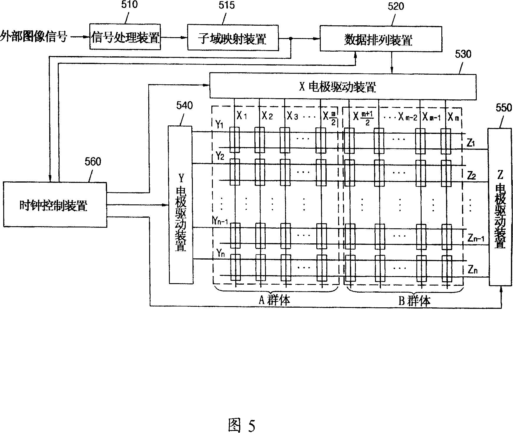
[0027] FIG. 5 is a block diagram of a driving device for a plasma display according to the present invention.

[0028] As shown in Figure 5, the driving device of the plasma display according to the present invention includes a signal processing device 510, a subfield mapping device 515, a data arrangement device 520, an X electrode driving device 530, a Y electrode driving device 540, a Z electrode driving device 550 and Clock control means 560 .

[0029] The signal processing device 510 converts the image signal input from the outside into image data consistent with driving the plasma display, and performs inverse gamma correction, gain correction and half toning.

[0030] The subfield mapping means 515 maps relevant subfields according to the image data input from the signal processing means 510 .

[0031] The data arrangement device 520 rear...


PUM


Abstract

This invention relates to a drive device of a plasma display including: a signal process device converting input image signals to image data, a sub-domain mapping device mapping related sub-domains based on the image data mappig relation, a data arranging device rearranging the image data according to the sub-domains, an X electrode drive device inputting the data pulses corresponding to the re-arranged image data in an addressing period into the X electrode, a Y electrode drive device inputting scan pulses into Y electrode in the addressing region and inputting maintenance pulse to the Y electrode, a Z electrode drive device inputting maintenance pulse to electrode Z alternately with the maintenance pulse input to electrode Y at the maintenance period and a clock control device inputting the data pulse into each of the unit cluster of level direction according to the X electrode drive device when the scan pulse is input into a related line.

Description

technical field [0001] The present invention relates to a driving device of a plasma display and a driving method thereof. More particularly, the present invention relates to a driving device of a plasma display capable of minimizing a load effect and a driving method thereof. Background technique [0002] FIG. 1 is a schematic diagram for explaining a conventional driving method of a plasma display. As shown in Figure 1, in order to use subfields to drive plasma displays, one frame time consists of n subfields, and each subfield can be divided into reset (reset) interval, address (address) interval and sustain ( sustain) interval. In FIG. 1, the number of subfields is 8, and the reset interval and the address interval are shown as one interval. In order to express brightness, the maintenance interval of each sub-field corresponds to a weight (weight) which is different from each other, and the brightness is represented by an appropriate combination of the weights. The w...

Claims


Application Information

Patent Timeline
Patent Type & Authority Applications(China)
IPC IPC(8): G09G3/28G09G3/20H01J17/49G09F9/313G09G3/296
Inventor 安炳桔朴成姬
Owner LG ELECTRONICS(NANJING) PLASMA CO LTD
Why Eureka
Try Eureka