
Safety switch

A safety switch and door switch technology, applied in the direction of electric switches, engineering safety devices, electrical components, etc., can solve the problems of unusable, cost increase, and large number of parts, and achieve the effect of reducing costs and reducing the number of parts

Active Publication Date: 2007-08-29
OMRON CORP
View PDF2 Cites 5 Cited by
  • Summary
  • Abstract
  • Description
  • Claims
  • Application Information

AI Technical Summary

Problems solved by technology

[0009] In the above-mentioned existing safety switch, in order to limit the entry of the actuator into the main body of the safety switch, the insertion port of the main body of the safety switch needs to be closed with a sealing piece, and in order to securely fix the sealing piece at the closed position, a lock needs to be used. The locking mechanism is locked, and it is necessary to rotate the closing piece between the closed position that closes the insertion opening and the opening position that opens the insertion opening, and the locking mechanism (pin lock) that locks the closing piece in the closed position. When the insertion port is opened through the closure piece, the locking mechanism is either carried by the operator or stored in a suitable storage place, which is troublesome to maintain and manage, and it can be said that if the locking mechanism is needed in case the locking mechanism is hidden. Problems such as inability to use without knowing the storage place and the custodian
In addition, as a safety switch, the number of parts is large, which also increases the cost

Method used


Image

  • Safety switch
  • Safety switch
  • Safety switch

Examples


Embodiment 1

[0064] Hereinafter, Embodiment 1 of the present invention will be described based on FIGS. 1 to 11 .

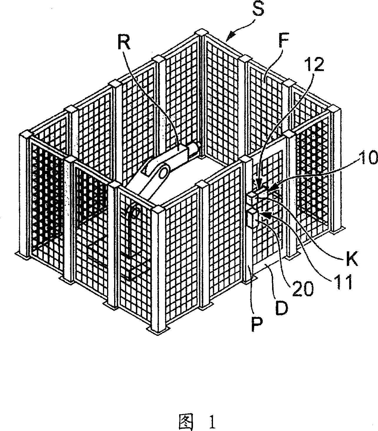
[0065] Reference sign S in FIG. 1 denotes a working area. The working area S surrounds the vicinity of the drive range of the machine, that is, the working manipulator R, with a guardrail F to ensure the surrounding safety, and a hinged opening and closing door D is provided at the entrance and exit of the guardrail F. And reference numeral 10 in FIG. 1 represents the safety switch of the present invention.

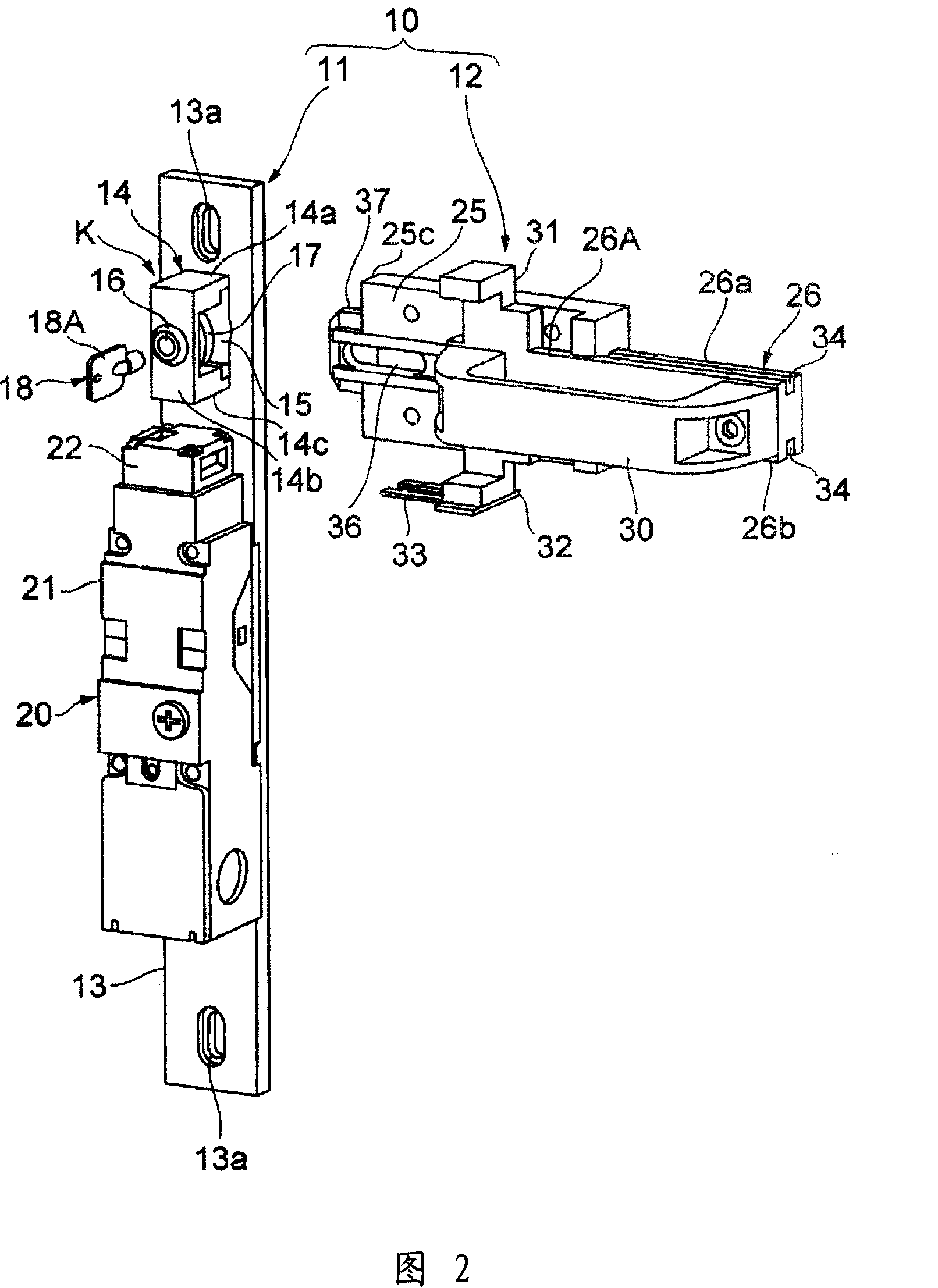
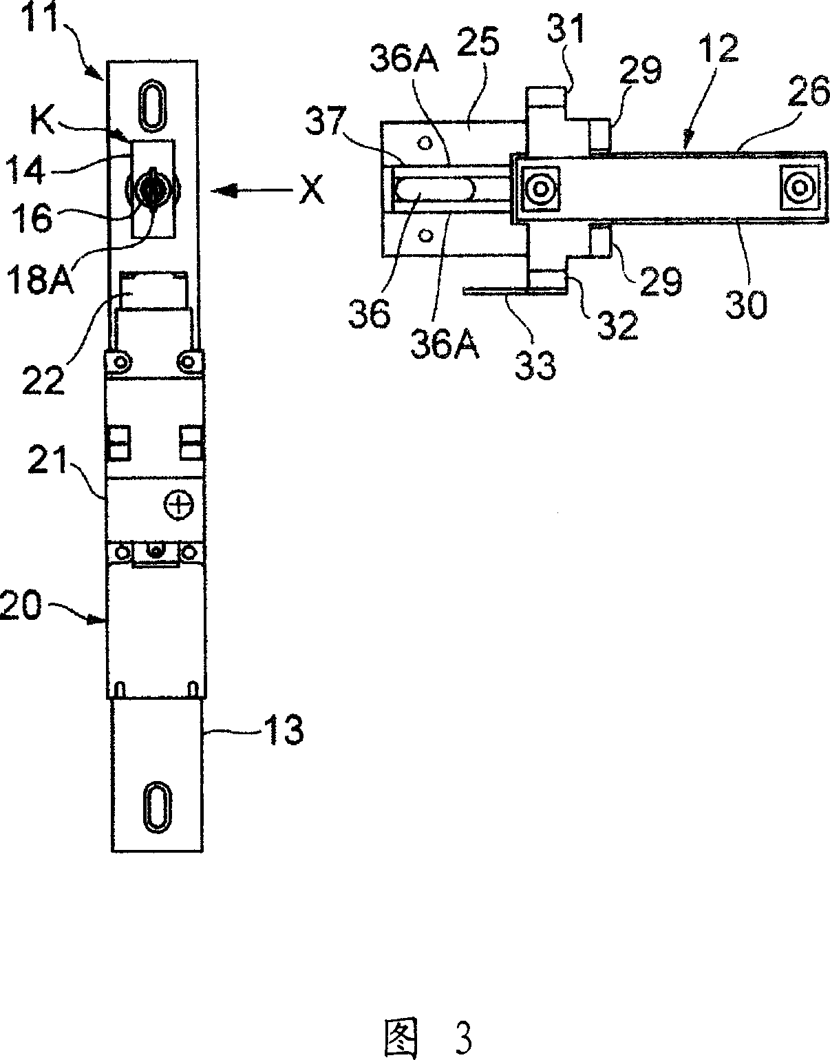
[0066] As shown in Figure 2, the safety switch 10 includes: a door switch unit 11 arranged on the pillar P forming the edge of the entrance and exit; a slider unit 12 arranged on the opening and closing door D, the door switch unit 11 and the slider unit 12 It is relative in the state where the opening and closing door D is closed.

[0067] The door switch unit 11 has a rectangular base 13 , and mounting holes 13 a are provided at upper and lower ends of the base 13 . ...

Embodiment 2

[0088] Hereinafter, Embodiment 2 of the present invention will be described with reference to FIGS. 12 to 19 .

[0089] In Embodiment 1 of the present invention described above, the slide key mechanism K is located on the door switch unit 11 side, but in Embodiment 2 of the present invention, the slide key mechanism K-1 is provided on the slider unit 12 side. Therefore, the guide 14 of the first embodiment of the present invention and the fitting hole 15 formed by the guide 14 do not exist on the door switch unit 11, and the slider 26 does not have the slider fitting of the first embodiment of the present invention. Only the protruding portion 35 exists on the front side of the slider main body 26A without the joint portion 37 . In Embodiment 2 of the present invention, the same reference numerals are attached to the same components and positions as those in Embodiment 1 of the present invention described above, and description thereof will be omitted.

[0090] The slide key ...

Embodiment 3

[0099] Hereinafter, Embodiment 3 of the present invention will be described based on FIGS. 20 to 27 .

[0100] In Embodiment 1 of the present invention described above, the slide key mechanism K is located on the door switch unit 11 side, but in Embodiment 3 of the present invention, the slide key mechanism K-2 is provided on the slider unit 12 side. Therefore, the guide 14 of the first embodiment of the present invention and the fitting hole 15 formed by the guide 14 do not exist on the door switch unit 11, and the slider 26 does not have the slider fitting of the first embodiment of the present invention. There is only the protruding portion 35 on the front side of the slider main body 26A without the joint portion 37 . In addition, in the third embodiment of the present invention, the same components and positions as those in the above-mentioned embodiment 1 of the present invention are assigned the same reference numerals, and description thereof will be omitted.

[0101]...


PUM


Abstract

The invention is a kind of safety switch which prevents troubles caused in the maintenance management of a locking mechanism and to reduce the cost using few parts. In order to carry out maintenance work on a work robot R, a worker pulls a handle 30 of a slider 26, and by making this slider 26 retreat, a slider fitting part 37 is extracted from a fitting hole part 15, and an actuator 33 is extracted out from an operation part 22 of a door-switch 20. In this case, a key 18 inserted into a key-hole 16a of a lock 16 is rotated by 90[deg.], and a protruding part 17A for intervention is turned toward the longitudinal direction so that fitting of the slider fitting part 37 to the fitting hole part 15 is inhibited. It is so arranged that only in this state can the key 18 be disengaged from the key-hole 16a of the lock 16.

Description

technical field [0001] The present invention relates to a safety switch that detects the open state of an opening and closing door that opens and closes an entrance and exit in a working area where a machine such as a working manipulator is installed to stop the driving of a machine. Background technique [0002] There is a working area that surrounds the driving range of a machine such as a working manipulator with a guardrail or the like to ensure the safety of the surrounding area. In order to ensure the safety of operators and the like who enter the interior, a safety switch that detects the open state of the door and stops the machine is installed on the door of the entrance and exit of such a work area. [0003] At present, as such a safety switch, for example, the following structure is constituted: when the opening and closing door is closed, the actuator is inserted into the main body of the safety switch so that the working manipulator can be moved; The main body ...

Claims


Application Information

Patent Timeline
Patent Type & Authority Applications(China)
IPC IPC(8): H01H9/28
CPCF16P3/08H01H27/002H01H9/28F16P3/10H01H3/16H01H3/20H01H9/00
Inventor 福本哲也主出阳一中西茂树佐佐木俊吉竹中英光嵨津谦治
Owner OMRON CORP
Features
  • Generate Ideas
  • Intellectual Property
  • Life Sciences
  • Materials
  • Tech Scout
  • Unparalleled Data Quality
  • Higher Quality Content
  • 60% Fewer Hallucinations
Learn More