Environment navigation device and program, system and method

An environmental management and air environment technology, applied in the field of environmental management procedures, can solve the problems of air comfort and specific guidance.

Active Publication Date: 2007-09-05
DAIKIN IND LTD
View PDF1 Cites 18 Cited by
  • Summary
  • Abstract
  • Description
  • Claims
  • Application Information

AI Technical Summary

Problems solved by technology

[0004] However, in existing devices, although guidance is given on whether it is within the comfort range, it may not be possible to provide specific

Method used


Image

  • Environment navigation device and program, system and method
  • Environment navigation device and program, system and method
  • Environment navigation device and program, system and method

Examples


no. 1 approach

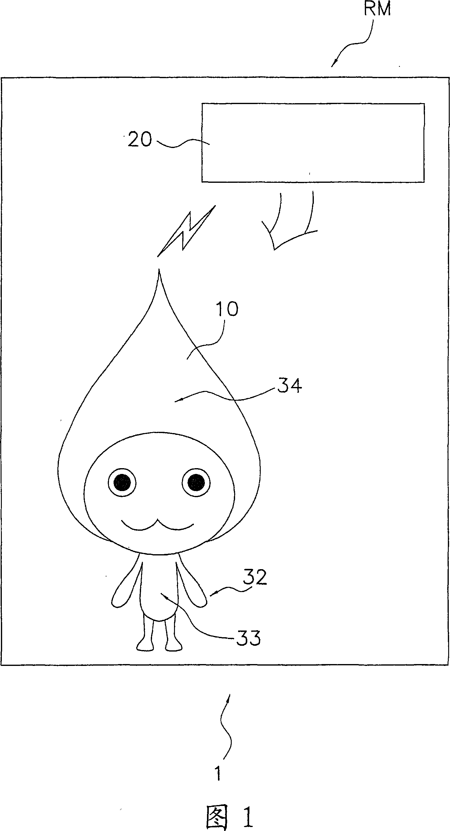
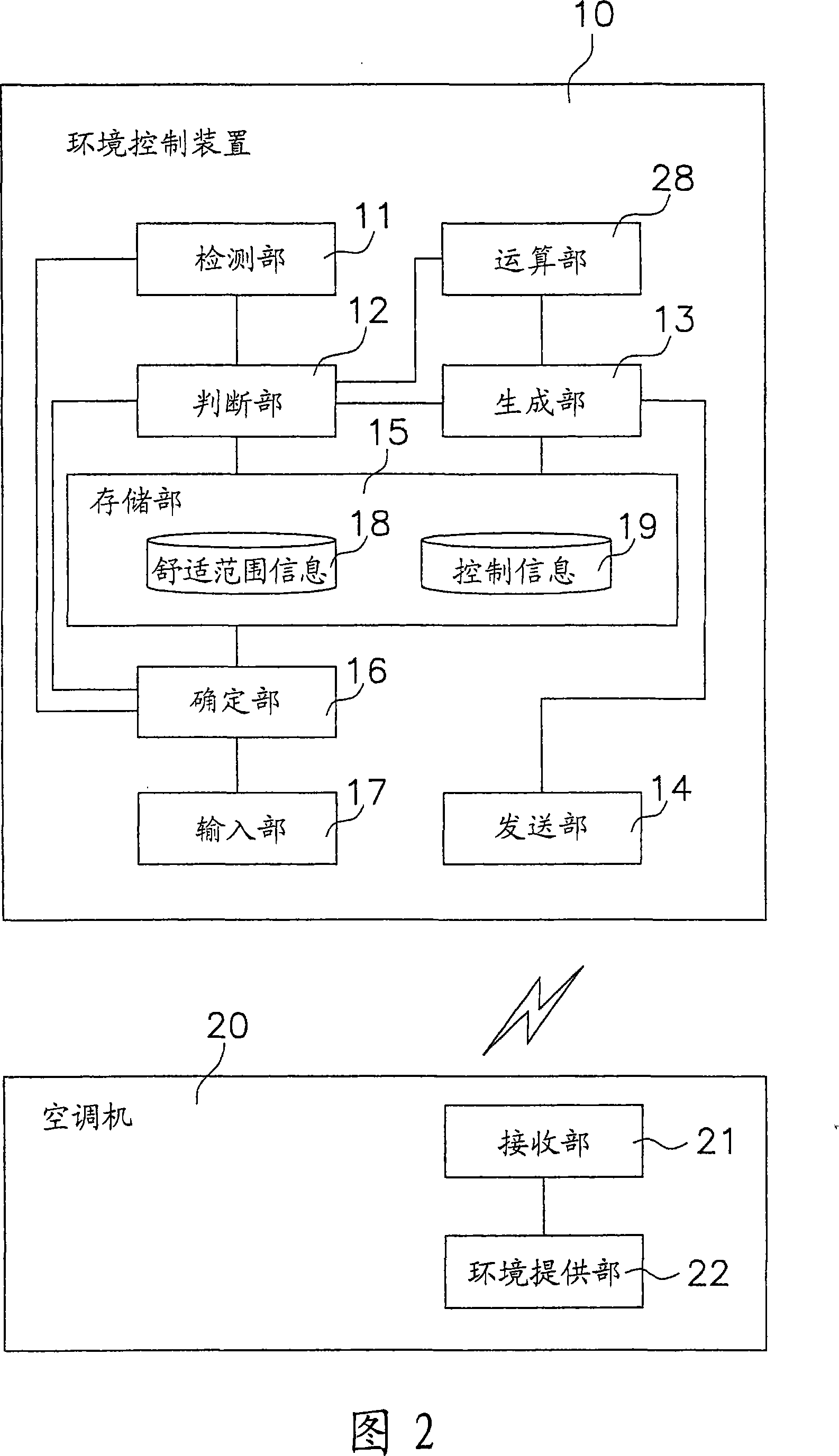
[0156] FIG. 1 shows a conceptual diagram of an environment control system 1 according to a first embodiment of the present invention. In addition, FIG. 2 shows a configuration diagram of components of the environment control system 1 according to the first embodiment of the present invention. The environment control system 1 shown in FIG. 1 is a system mainly for controlling the air-conditioning environment of indoor RM.

[0157]

[0158] The environment control system 1 shown in FIG. 1 mainly includes an environment control device 10 and an air conditioner 20 . The environmental control device 10 is installed in the indoor RM and can be transported. The environment control device 10 has, for example, an outer shape of ぴちよんくん (registered trademark). The air conditioner 20 mainly tempers the air environment of the indoor RM (see FIG. 1 ).

[0159]

[0160] As shown in FIG. 2 , the environment control device 10 shown in FIG. 1 mainly includes a detection unit 11 , a deter...

no. 2 approach

[0218] FIG. 11 shows a conceptual diagram of an environment control system 100 according to a second embodiment of the present invention. 12 shows a configuration diagram of each component of an environment control system 100 according to a second embodiment of the present invention. In FIGS. 11 and 12 , the same reference numerals denote the same constituent elements as those of the environmental control system 1 in FIGS. 1 and 2 . The environment control system 100 shown in FIG. 11 is a system mainly for controlling the air-conditioning environment of indoor RM. The environmental control device 110 is installed in the indoor RM and can be transported.

[0219] As shown in Fig. 11 and Fig. 12, although the basic structure of the environmental control system 100 is the same as that of the first embodiment, and each structural element is the same as that of Fig. 2, as shown in Fig. 11, the difference from the first embodiment lies in the environment The control device 10 is a...

no. 3 approach

[0228] FIG. 15 shows a conceptual diagram of an environment guidance device 210 according to a third embodiment of the present invention. Furthermore, FIG. 16 shows a configuration diagram of components of an environmental guidance device 210 according to a third embodiment of the present invention. The environmental guidance device 210 shown in FIG. 15 is mainly installed in the indoor RM and can be transported. As shown in FIG. 15 , the environmental guidance device 210 has, for example, an outer shape of ぴちよんくん (registered trademark).

[0229]

[0230] As shown in FIG. 16 , the environmental guidance device 210 shown in FIG. 15 mainly includes a detection unit 211 , a determination unit 212 , a suggestion unit 213 , a sound generation unit 214 , and a storage unit 215 .

[0231] The detecting unit 211 shown in FIG. 16 detects the air environment of the indoor RM (see FIG. 15 ). The determination unit 212 receives information on the air environment of the indoor RM from ...


PUM


Abstract

The invention provides an environmental control apparatus, an environmental control system, an environmental control method, and an environmental control program that can create a sufficiently comfortable air environment in a room. An environmental control apparatus (10, 10a, 110, 110a, 210, 310) that is installed in a room and is portable, comprises a sensor unit (11. 211), a determination unit (12, 12a, 212), and an output unit (14, 213). The sensor unit senses the air environment of the room. The determination unit determines whether the air environment of the room is within the range of a comfort zone based on information about the air environment of the room. The output unit, based on at least the information about the determination result of the determination unit, outputs information or a signal in order to make the air environment of the room fall within the range of the comfort zone.

Description

technical field [0001] The present invention relates to an environment management device, an environment management system, an environment management method and an environment management program. Background technique [0002] Conventionally, there have been proposed devices that monitor and display whether a room is within a comfortable range. (For example, refer to Patent Document 1.). [0003] Patent Document 1: Japanese Patent Laid-Open No. 6-207734 (pages 1-8, Figs. 1-9) [0004] However, in the existing device, although guidance is given as to whether it is within the comfort range, it may not be possible to provide specific guidance on how to make the room stay within the comfort range. Therefore, there is a possibility that the air in the room cannot be sufficiently comfortable. Contents of the invention [0005] An object of the present invention is to provide an environment management device, an environment management system, an environment management method, a...

Claims


Application Information

Patent Timeline
IPC IPC(8): F24F11/02
Inventor 西村政弥
Owner DAIKIN IND LTD
Why Eureka
Try Eureka