Refrigerating system of air-conditioning and method for controlling flow of refrigerant

A refrigerant flow, air-conditioning refrigeration technology, applied in the direction of air-conditioning systems, heating and ventilation control systems, refrigerators, etc., to achieve the effect of real-time control and adjustment

Active Publication Date: 2011-02-02
HAIER GRP CORP +1
View PDF7 Cites 2 Cited by
  • Summary
  • Abstract
  • Description
  • Claims
  • Application Information

AI Technical Summary

Problems solved by technology

[0003] In the technical solution of this invention, a capillary tube is set between the outlet of the outdoor unit heat exchanger and the suction port of the compressor, and the evaporation of the refrigerant on the capillary tube is used to To simulate the evaporation of indoor unit refrigerant in the evaporator, but the temperature measured by this simulation method is not accurate and cannot accurately reflect the working conditions of the indoor unit. In addition, the outdoor unit cannot know the temperature of the indoor unit heat exchanger, only Simple simulation can be performed, so the adjustment of the opening of the electronic expansion valve cannot be accurate and timely

Method used


Image

  • Refrigerating system of air-conditioning and method for controlling flow of refrigerant
  • Refrigerating system of air-conditioning and method for controlling flow of refrigerant
  • Refrigerating system of air-conditioning and method for controlling flow of refrigerant

Examples


Embodiment Construction

[0042] Preferred embodiments of the present invention will be described in detail below with reference to the accompanying drawings.

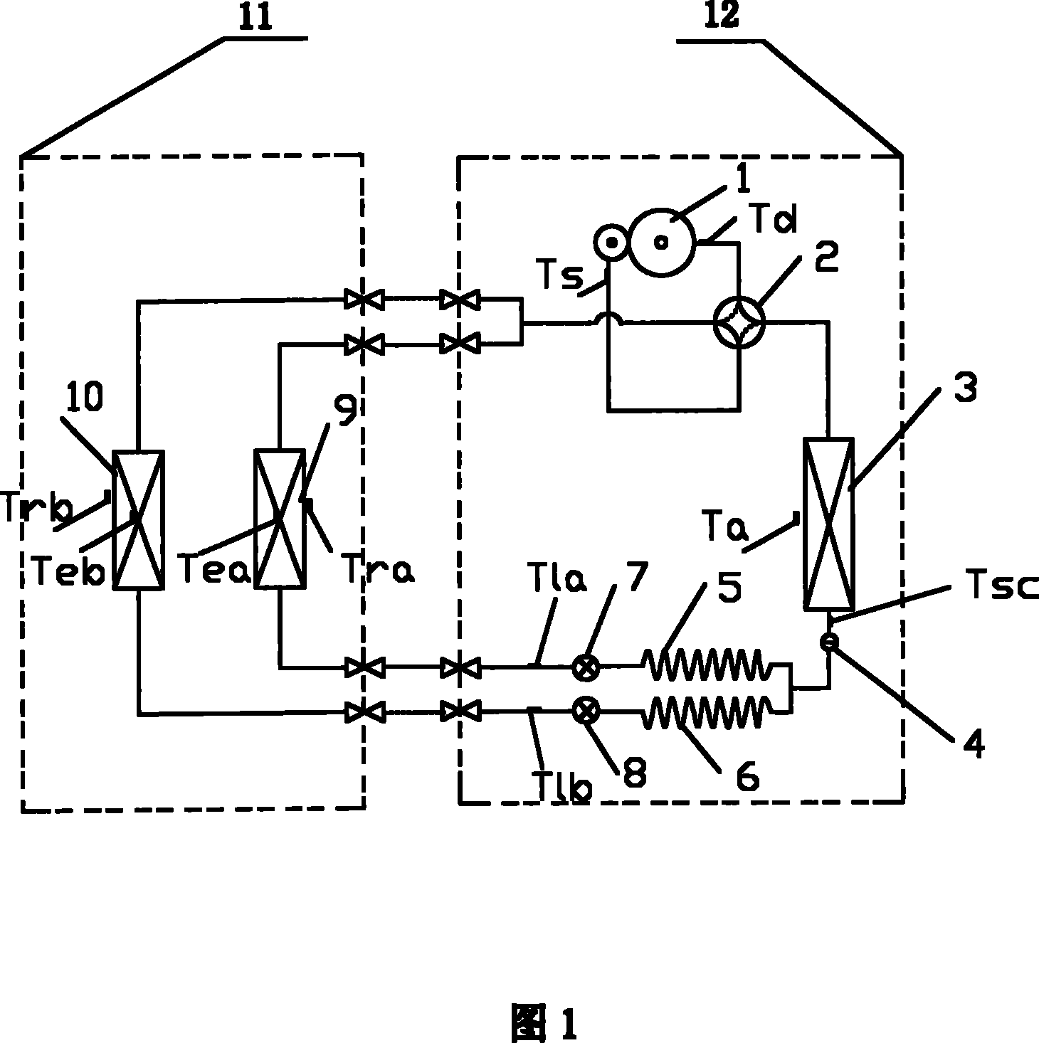
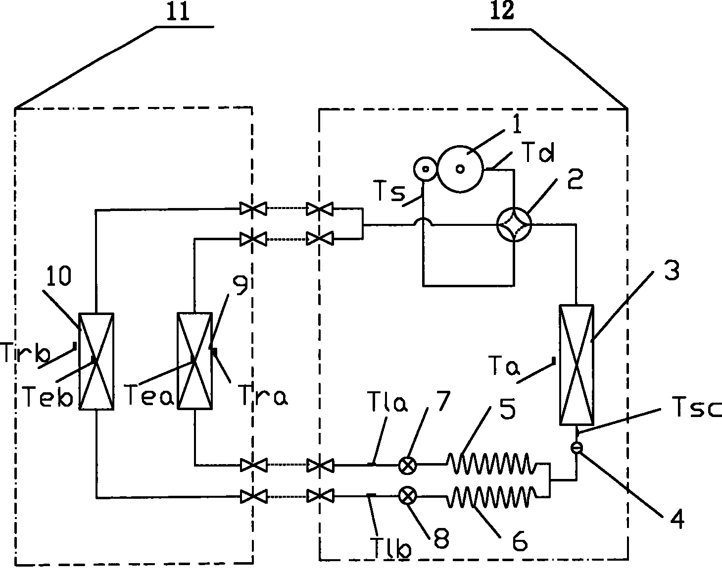
[0043] refer to figure 1 As shown, the compressor 1 , the four-way reversing valve 2 , and the outdoor heat exchanger 3 of the air-conditioning and refrigeration system are arranged on the outdoor unit 12 . This preferred embodiment is a one-to-two air conditioner with two indoor heat exchangers, which are respectively the indoor heat exchanger 9 of the A unit and the indoor heat exchanger 10 of the B unit, which are arranged on the indoor unit 11 . The two ports of the four-way reversing valve 2 are connected to the exhaust end and the intake end of the compressor 1, and the other two ports of the four-way reversing valve 2 are respectively connected to the outdoor heat exchanger 3 and the indoor heat exchanger of the A unit 9 and B engine room heat exchanger 10, wherein, A machine room heat exchanger 9 and B engine room heat exchanger 10 ar...


PUM


Abstract

The present invention discloses an air conditioner refrigerating system. A compressor, a four-way reversing valve and an outdoor heat exchanger are disposed on the outdoor machine. An indoor heat exchanger is disposed on the indoor machine. Two ports of the four-way reversing valve are connected to the air intake end and the air discharge end of the compressor, and another two ports of the four-way reversing valve are respectively connected to the outdoor heat exchanger and indoor heat exchanger. a capillary is connected between the outdoor heat exchanger and the indoor heat exchanger, an electronic expand valve is disposed between the capillary and the indoor heat exchanger, a liquid pipe temperature sensing apparatus is disposed between the electronic expand valve and the indoor heat exchanger, a inspiration temperature sensing apparatus is disposed at the air intake port of the compressor. The present invention also discloses a control method for refrigerant flux.

Description

technical field [0001] The invention relates to an air-conditioning technology, in particular to an air-conditioning refrigeration system and a refrigerant flow control method. Background technique [0002] Chinese Patent No. 98110372.3 discloses a refrigeration system for one-to-many air conditioners, including a compressor, a liquid receiver, a four-way valve, a dry filter, a muffler, an outdoor heat exchanger, corresponding pre-cooling capillary tubes, and an indoor heat exchange There is a corresponding electronic expansion valve with a certain pulse range between each indoor heat exchanger and its corresponding supercooling capillary, and a compressor exhaust valve is installed between the compressor and the four-way valve. The air temperature measuring point Ti is provided with a corresponding cooling outlet temperature measuring point Ti (i: a natural number above 5) at the cooling outlet end of the indoor heat exchanger, between the pre-cooling capillaries correspon...

Claims


Application Information

Patent Timeline
Patent Type & Authority Patents(China)
IPC IPC(8): F24F1/00F24F11/00F25B41/04F25B49/02
Inventor 王召兴谷东照梁晓东王勇付裕
Owner HAIER GRP CORP
Why Eureka
Try Eureka