Spray arm bearing and dishwasher with a spray arm arrangement

A spray arm, dishwasher technology, applied to spray devices, dishwashers/washers for tableware, spray devices with movable outlets, etc., can solve problems such as consumption

Inactive Publication Date: 2007-10-03
ELECTROLUX HOME PROD CORP NV
View PDF0 Cites 1 Cited by
  • Summary
  • Abstract
  • Description
  • Claims
  • Application Information

AI Technical Summary

Problems solved by technology

Both methods are therefore expensive, since multiple processing steps or complex injection tools are necessary

Method used


Image

  • Spray arm bearing and dishwasher with a spray arm arrangement
  • Spray arm bearing and dishwasher with a spray arm arrangement

Examples


Embodiment Construction

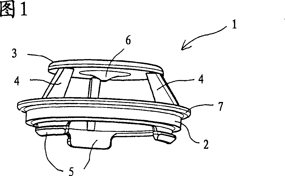
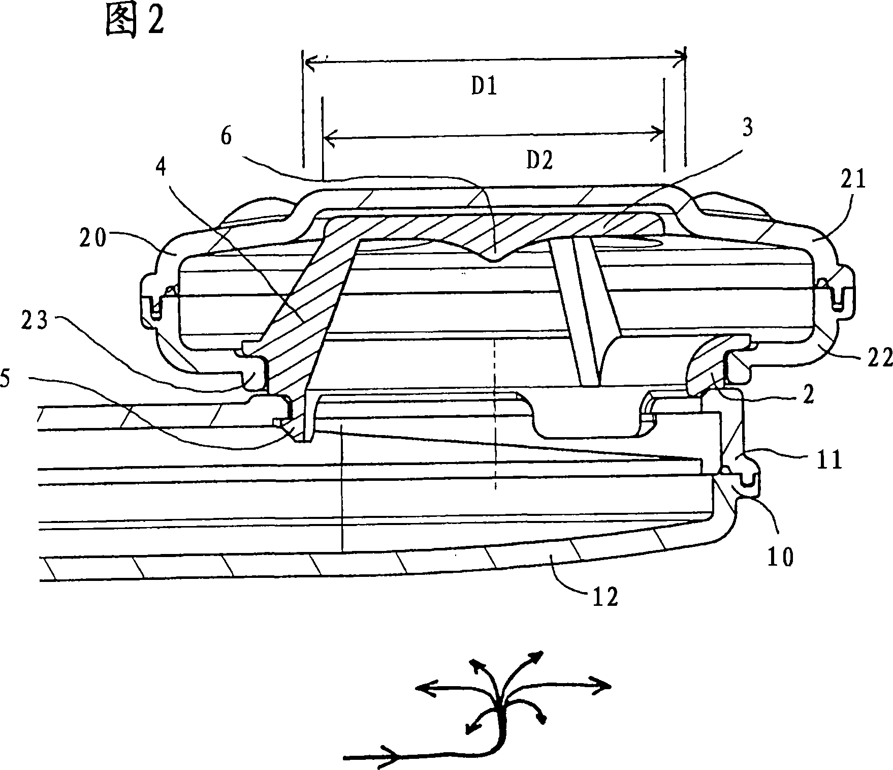
[0010] FIG. 1 shows a perspective view of a spray arm bearing 1 . As shown in cross section in FIG. 2 , the spray arm bearing 1 is used to connect an inlet piece 10 for feeding rinsing liquid to a spray arm 20 , which is rotatably mounted on the spray arm bearing 1 . The spray arm bearing 1 comprises a bearing ring 2 with an outer bearing surface which is delimited in the axial direction (upward as depicted in FIG. 1 ) by an annular projection 7 . A top 3 serving as a flow guide is connected to the bearing ring 2 via ribs 4 . In the axial cross-section, the ribs 4 extend substantially in the radial direction and have the smallest width in the circumferential direction, so that the ribs 4 offer less flow resistance to a liquid flow deflected in the radial direction. On the side opposite the top 3, an axially protruding stop 5 is arranged on the bearing ring 2, with which stop the spray arm bearing 1 snaps into the outlet on the inlet part 10 (FIG. 2) .

[0011] A hyperbolic ...


PUM


Abstract

The invention relates to a spray arm bearing (1), comprising a bearing element (2) for supporting a spray arm (20) and a flow guiding device (3) connected to the bearing element (2), wherein the bearing element (2 ) has a through hole for the passage of liquid. According to the invention, the base ( D2 ) of the flow guiding device ( 3 ) corresponds to the base ( D1 ) of the through-opening or lies within the base ( D1 ) of the through-opening.

Description

technical field [0001] The invention relates to a spray arm bearing for rotatably mounting a spray arm on a liquid inlet piece. Background technique [0002] Conventional spray arm bearings comprise a bearing ring with a bearing surface or bearing seat on which the spray arm is rotatably mounted. An impingement surface is connected to the bearing ring, which deflects the liquid flow flowing axially through the bearing ring from an axial flow direction to a radial flow direction, so that the liquid flow enters into the side of the spray arm. The impact surface is connected to the bearing ring, so that the recoil caused by the deflection is conducted away via the bearing ring and does not itself act on the spray arm. As a result, the axial forces are reduced and the static or sliding friction is significantly reduced when such a spray arm is mounted. In the production of conventional spray arm bearings either the impact surface and the bearing ring are first manufactured sep...

Claims


Application Information

Patent Timeline
Patent Type & Authority Applications(China)
IPC IPC(8): A47L15/23
CPCB05B3/026A47L15/23Y10T137/3031Y10T137/3034
Inventor F·马克W·施密特
Owner ELECTROLUX HOME PROD CORP NV
Why Eureka
Try Eureka