A fully automatic glue injection machine

A glue injection machine, fully automatic technology, applied in the field of glue injection machine, can solve the problems of inaccurate pouring, high labor cost, low efficiency, etc., and achieve the effect of improving product quality, avoiding height inaccuracy, and high glue injection precision.

Active Publication Date: 2016-12-28
上海华银电器有限公司
View PDF6 Cites 0 Cited by
  • Summary
  • Abstract
  • Description
  • Claims
  • Application Information

AI Technical Summary

Problems solved by technology

[0003] 1. The efficiency is low. Due to the slow speed of manual pouring and moving, the production efficiency of manual pouring is far lower than that of machine automatic pouring;
[0004] 2. Inaccurate pouring, manual pouring often pours resin outside the core coil slot, resulting in material waste and product quality defects;
[0005] 3. The amount of glue injection is inaccurate. The technical requirements often stipulate that the pouring liquid level should not be lower than the parameters of the coil core surface, such as 0.8mm or 0.5mm. However, it is difficult to control the liquid level height by manual pouring, which may easily lead to products that do not meet the requirements and cause Cause unnecessary waste of materials;
[0006] 4. Insufficient resin filling. The injection table for manual injection usually has no electric heating function. After the resin is poured into the product, the fluidity is not enough to fully fill the coil core, resulting in product quality defects;
[0007] 5. Manual pouring requires a lot of labor costs

Method used


Image

  • A fully automatic glue injection machine
  • A fully automatic glue injection machine

Examples


Embodiment Construction

[0030] The present invention will be described in detail below in conjunction with the accompanying drawings and specific embodiments.

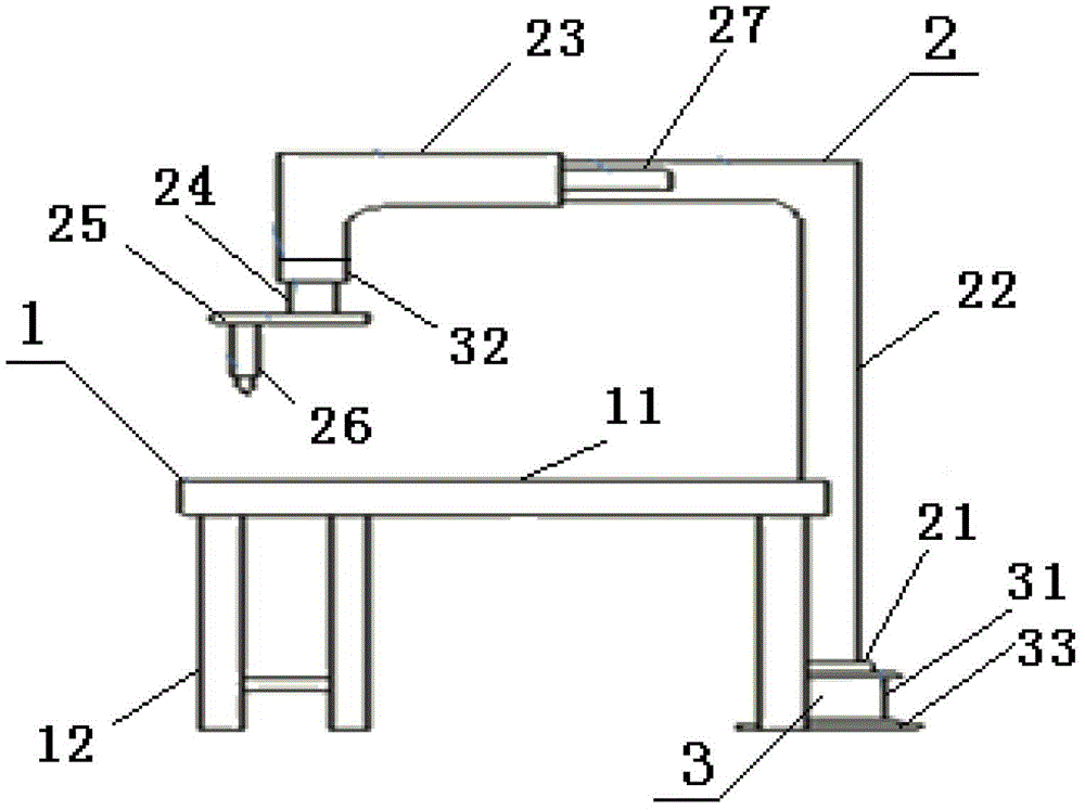
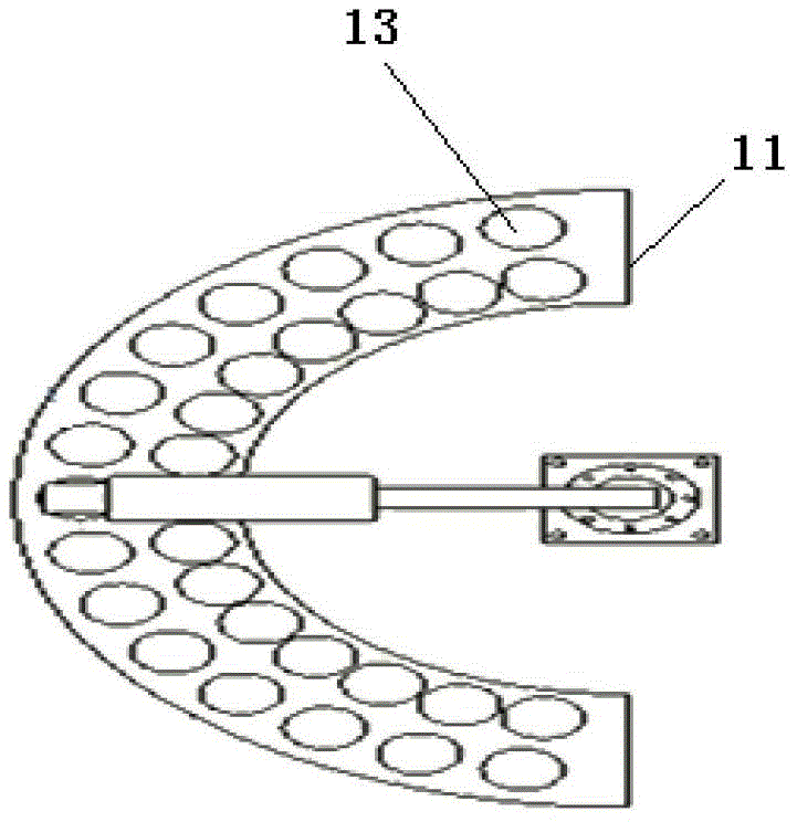
[0031] Such as figure 1 As shown, a fully automatic glue injection machine is used for pouring workpieces. It is characterized in that it includes a glue injection table 1, a glue injection arm 2 and a drive mechanism 3, and the glue injection arm 2 is connected with the drive mechanism 3. The injection The glue arm 2 includes a rotary table 21, a rotary boom 22, a pneumatic sliding arm 23, a rotary pouring arm 24, a rotary disk 25 and a glue injection nozzle 26, and the drive mechanism 3 includes a first servo motor 31, a second servo motor 32, Motor base 33 and controller.

[0032] Both the first servo motor 31 and the second servo motor 32 are connected to the controller, the motor base 33 is fixed to the support surface, the first servo motor 31 is located on the motor base 33, and is connected to the rotary table 21 in transmission, so ...


PUM


Abstract

The present invention relates to a full automatic glue injection machine, which comprises a glue injection table, a glue injection arm and a drive mechanism, wherein the glue injection arm comprises a rotation table, a rotation suspending arm, a pneumatic sliding arm, a rotation casting arm, a rotation disk and a glue injection nozzle, one end of the rotation suspending arm is connected with the drive mechanism through the rotation table, the other end is connected with the pneumatic sliding arm, the pneumatic sliding arm is connected with the rotation casting arm, and the rotation casting arm is connected with the glue injection nozzle through the rotation disk. According to the present invention, when the full automatic glue injection machine works, a work-piece is placed on the glue injection table, the driving mechanism drives the rotation table to rotate so as to drive the rotation suspending arm to perform rotation movement, the pneumatic sliding arm moves along the rotation suspending arm, the drive mechanism drives the rotation suspending arm to drive the rotation disk to rotate when the rotation suspending arm is accurately positioned just above the work-piece to be casted, and the rotation disk drives the glue injection nozzle to align to the work-piece to be casted to cast. Compared with the full automatic glue injection machine in the prior art, the full automatic glue injection machine of the present invention has advantages of simple operation, accurate positioning, low energy consumption, high glue injection precision, high production efficiency, cost saving and the like.

Description

technical field [0001] The invention relates to a glue injection machine, in particular to a fully automatic glue injection machine which can be used for pouring larger workpieces. Background technique [0002] The traditional automatic glue injection machine usually fixes the position of the glue injection nozzle, and the conveyor belt drives the workpiece to the station and automatically injects glue. Due to the limitation of the conveyor belt itself, this kind of machine is only suitable for smaller and lighter workpieces. For larger workpieces, such as the pouring of brake cores, the method of manual pouring is usually still used, and the method of manual pouring has the following disadvantages: [0003] 1. The efficiency is low. Due to the slow speed of manual pouring and moving, the production efficiency of manual pouring is far lower than that of machine automatic pouring; [0004] 2. Inaccurate pouring, manual pouring often pours resin outside the core coil slot, re...

Claims


Application Information

Patent Timeline
Patent Type & Authority Patents(China)
IPC IPC(8): B29C39/24B29C39/10
Inventor 陈继华金旭峰李瑞杰
Owner 上海华银电器有限公司
Why Eureka
Try Eureka