High-precision liquid crystal display plastic shell and processing method

A liquid crystal display and plastic casing technology, which is applied in the field of high-precision liquid crystal display plastic casing and processing, can solve the problems of reducing production efficiency, affecting product production, and narrow space for construction, so as to improve assembly efficiency, increase production efficiency, The effect of ensuring the molding quality

Active Publication Date: 2021-03-02
合茂电子元件(吴江)有限公司
View PDF11 Cites 0 Cited by
  • Summary
  • Abstract
  • Description
  • Claims
  • Application Information

AI Technical Summary

Problems solved by technology

[0006] The object of the present invention is to provide a high-precision liquid crystal display plastic casing and processing method, which has the advantages of convenient assembly of the casing, and can avoid feeding blockage and feeding interruption, and solve the problem that the traditional display casing is processed into a whole Yes, such a shell is very inconvenient in the later assembly. When installing the screen and other components, it is limited by the shell. The space for construction is narrow, and the precise parts are not easy to align and fix, which will cause slow installation and reduce production efficiency. , and when the traditional injection molding machine is feeding, as the material in the storage assembly decreases, the feeding pipe will not be able to touch the material, resulting in intermittent feeding of the injection molding machine, affecting the normal production of the product and affecting the quality of the product. If the feeding pipe is too long, it will be inserted into the material. During the feeding, it is easy to cause the feeding pipe to be blocked and also affect the production of the product.

Method used


Image

  • High-precision liquid crystal display plastic shell and processing method
  • High-precision liquid crystal display plastic shell and processing method
  • High-precision liquid crystal display plastic shell and processing method

Examples


Embodiment Construction

[0030] The following will clearly and completely describe the technical solutions in the embodiments of the present invention with reference to the accompanying drawings in the embodiments of the present invention. Obviously, the described embodiments are only some, not all, embodiments of the present invention. Based on the embodiments of the present invention, all other embodiments obtained by persons of ordinary skill in the art without making creative efforts belong to the protection scope of the present invention.

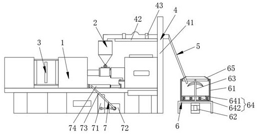
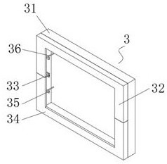
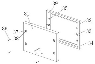
[0031] see Figure 1-4 , the present invention provides a technical solution, a high-precision liquid crystal display plastic housing, including injection molding equipment 1 and a housing body 3 located inside the injection molding equipment 1, the housing body 3 includes a rear shell 31, and the rear shell 31- The top and the bottom of the side are respectively provided with a top front case 32 and a bottom front case 34, and the top front case 32 and the bott...


PUM

PropertyMeasurementUnit
Melting pointaaaaaaaaaa

Abstract

The invention discloses a high-precision liquid crystal display plastic shell and a processing method. The high-precision liquid crystal display plastic shell comprises an injection molding device anda shell body located in the injection molding device, the shell body comprises a rear shell, and a top front shell and a bottom front shell are arranged at the top and the bottom of one side of the rear shell correspondingly, and the top front shell and the bottom front shell are fixedly installed together through an assembly. When the shell body is produced, the feeding structure of the injection molding equipment is innovated, so that a feeding end of a feeding device is always located above a material and keeps in contact with the material, the situation that the feeding device is blockedby the material and cannot make contact with the material is avoided, continuous feeding can be guaranteed, and the molding quality of a product is guaranteed; and the shell body is divided into threeparts to be produced, so that a display screen is more convenient in the later assembling procedure, enough space can be reserved in the shell, a user can conveniently install and place precise parts, and therefore the assembling efficiency and the production efficiency are improved.

Description

technical field [0001] The invention relates to the technical field of liquid crystal display casing processing, in particular to a high-precision liquid crystal display plastic casing and a processing method. Background technique [0002] Liquid crystal display is a flat and ultra-thin display device. It is composed of a certain number of color or black and white pixels and is placed in front of a light source or reflective surface. The power consumption of liquid crystal displays is very low, so it is favored by engineers and is suitable for electronic devices that use batteries , its main principle is to stimulate the liquid crystal molecules to generate points, lines, and surfaces to form a picture with the back lamp tube. The working principle of the liquid crystal display: liquid crystal is a special substance between solid and liquid. It is an organic The compound is liquid under normal conditions, but its molecular arrangement is as regular as that of solid crystals,...

Claims


Application Information

Patent Timeline
IPC IPC(8): B29C45/03B29C45/18B29C45/17B29C45/64B29C65/56
CPCB29C45/03B29C45/18B29C45/17B29C45/64B29C65/56
Inventor 李勇蔡月青胡珊霞
Owner 合茂电子元件(吴江)有限公司
Why Eureka
Try Eureka