Fan, bearing structure and its oil bearing

A bearing and shaft hole technology, which is applied in the directions of bearing elements, shafts and bearings, components of pumping devices for elastic fluids, etc., can solve the problems of shortened service life of oil-impregnated bearings 10, unsmooth overall operation, and limited utility, etc. Achieve the effect of reducing up and down vibration and air hammer, avoiding friction, reducing consumption and volatilization

Inactive Publication Date: 2010-05-12
DELTA ELECTRONICS INC
View PDF0 Cites 1 Cited by
  • Summary
  • Abstract
  • Description
  • Claims
  • Application Information

AI Technical Summary

Problems solved by technology

Especially when the oil-impregnated bearing 10 is used upside down, the situation of leakage will be more serious, and then the service life of the oil-impregnated bearing 10 will be shortened, or the contact between the rotating shaft 11 or the sleeve 12 and the oil-impregnated bearing will be damaged due to insufficient lubricating oil. The friction force between them is too large, causing the overall operation to be unsmooth
[0004] To solve this problem, please refer to figure 2 As shown, the top surface 102 of the oil bearing 10 is provided with a sealing partition 13 to block the way of lubricating oil leakage, but the effect is limited, the lubricating oil will still come from the gap between the oil bearing 10 and the rotating shaft 11, And the gap between the oil bearing 10 and the sleeve 12 leaks outward

Method used


Image

  • Fan, bearing structure and its oil bearing
  • Fan, bearing structure and its oil bearing
  • Fan, bearing structure and its oil bearing

Examples


Embodiment Construction

[0039] A fan, a bearing structure and an oil-impregnated bearing thereof according to preferred embodiments of the present invention will be described below with reference to related drawings, wherein the same elements will be described with the same reference symbols.

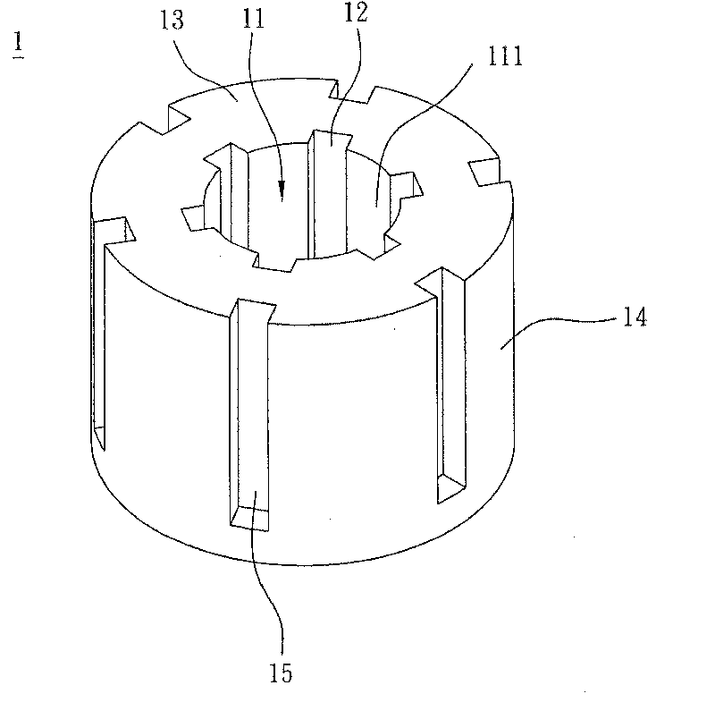
[0040] Please refer to image 3 As shown, an oil-impregnated bearing 1 according to a preferred embodiment of the present invention includes a shaft hole 11 and a plurality of first grooves 12 . In this embodiment, each first groove 12 is disposed on a wall surface 111 of the shaft hole 11 and extends to the top surface 13 of the oil bearing 1 . Each of the first grooves 12 extends parallel to the axial direction of the shaft hole 11 , or extends spirally on the wall surface 111 of the shaft hole 11 (not shown).

[0041] The outer periphery 14 of the oil-impregnated bearing 1 can also form a plurality of second grooves 15, and each second groove 15 can correspond to the first grooves 12, or be formed between ...


PUM


Abstract

The present invention discloses an oilness bearing which includes an axle hole and a plurality of grooves. Each groove extends from the inner wall of the bearing to the outer wall of the bearing through the top surface of the bearing, and can effectively guide the lubricant oil gas in the bearing to flow.

Description

technical field [0001] The invention relates to a fan, a bearing structure and its oil bearing (sleeve bearing), in particular to a fan, a bearing structure and its oil bearing which reduce the consumption and volatilization of lubricating fluid. Background technique [0002] Motors have been widely used in vehicles, fans, water pumps, and computer peripherals (such as printers, scanners, etc.), and the bearing structure in the motor directly affects the quality of the motor. In order to enhance the self-lubrication and impact resistance of bearings, oil-impregnated bearings are often used. The existing oil-impregnated bearings are made of porous materials, with many fine holes inside and contain lubricating oil. When a rotating bearing rotates, the oil-impregnated bearing Through the capillary phenomenon of the fine holes, the lubricating oil can fill the gap between the rotating shaft and the oil bearing to achieve the effect of lubrication. [0003] Please refer to figu...

Claims


Application Information

Patent Timeline
Patent Type & Authority Patents(China)
IPC IPC(8): F16C33/10F04D29/056
Inventor 徐伟峻张楯成黄文喜
Owner DELTA ELECTRONICS INC
Why Eureka
Try Eureka