Simple automobile electronically controlled engine training bench

A technology of electronically controlled engines and training platforms, which is applied in the direction of educational appliances, instruments, teaching models, etc., can solve the problems of high frequency and amplitude of engine vibration, misoperation, and unfavorable observation and recording of display device vibration, so as to slow down the up and down vibration , the effect of reducing vibration

Pending Publication Date: 2017-11-07
林顺宝
View PDF0 Cites 1 Cited by
  • Summary
  • Abstract
  • Description
  • Claims
  • Application Information

AI Technical Summary

Problems solved by technology

[0002] With the rapid development of electronically controlled engine technology, it is difficult to solve complex fault problems based on traditional experience in the current automobile maintenance work order, which requires maintenance workers to have certain knowledge and superb maintenance skills on automobile electrician and electronic control
[0003] The current electronically controlled training bench used by schools and training institutions to assist teaching usually fixes the real engine on the bottom plate of the training bench, and simulates various faults and repairs through the control device and display device of each module. However, in actual operation, the vibration frequency and amplitude of the training engine during work are very large, driving the entire training platform to vibrate, which will easily cause the trainees to misoperate the control device during the operation process, and the vibration of the display device is not conducive to Observation and recording, for this purpose a simple vehicle electronically controlled engine training platform is proposed to solve the above problems

Method used


Image

  • Simple automobile electronically controlled engine training bench
  • Simple automobile electronically controlled engine training bench
  • Simple automobile electronically controlled engine training bench

Examples


Embodiment Construction

[0018] The following will clearly and completely describe the technical solutions in the embodiments of the present invention with reference to the accompanying drawings in the embodiments of the present invention. Obviously, the described embodiments are only some, not all, embodiments of the present invention. Based on the embodiments of the present invention, all other embodiments obtained by persons of ordinary skill in the art without making creative efforts belong to the protection scope of the present invention.

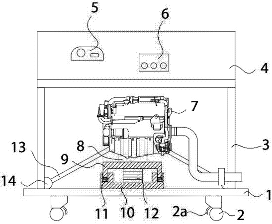
[0019] see Figure 1-4 , the present invention provides a technical solution: a simple automobile electronically controlled engine training platform, including a base plate 1, a universal wheel 2 is provided at the bottom of the base plate 1, and a wheel lock 2a is provided on the universal wheel 2. The structure of the steering wheel 2 facilitates the movement of the entire training platform, and is fixed by the wheel lock 2a. The top surface of the bottom pl...


PUM


Abstract

The invention discloses a simple automobile electric control engine training platform, which comprises a bottom plate and a frame plate, the engine is located on the bottom plate inside the frame plate, the bottom end of the engine is fixedly connected with an upper buffer plate, and the upper buffer plate and the lower buffer block are connected A rubber column is fixedly connected, and a support rod is fixedly installed around the lower end of the engine, the support rod connects two connecting rods, the connecting rod connects a slide block, and the slide block is movably sleeved on the slide rod. The structure of the present invention drives the installation base to move up and down due to the up and down vibration generated when the engine is working, so that the upper buffer plate moves up and down relative to the lower buffer plate, and then compresses the rubber column to achieve the effect of slowing down the up and down vibration of the engine. The vibration on the top makes the support rod reciprocate in the direction of movement to the inside and outside, and the connecting rod drives the slider to reciprocate on the slide rod. The shock absorbing spring can slow down this movement, so the effect of slowing down the vibration of the engine is achieved.

Description

technical field [0001] The invention relates to the field of teaching aid benches, in particular to a simple automobile electric control engine training bench. Background technique [0002] With the rapid development of electronically controlled engine technology, it is difficult to solve complex fault problems based on traditional experience in the current automobile maintenance work order, which requires maintenance workers to have certain knowledge and superb maintenance skills on automobile electrician and electronic control . [0003] The current electronically controlled training bench used by schools and training institutions to assist teaching usually fixes the real engine on the bottom plate of the training bench, and simulates various faults and repairs through the control device and display device of each module. However, in actual operation, the vibration frequency and amplitude of the training engine during work are very large, driving the entire training platf...

Claims


Application Information

Patent Timeline
Patent Type & Authority Applications(China)
IPC IPC(8): G09B25/02
CPCG09B25/02
Inventor 林顺宝帅宗良
Owner 林顺宝
Why Eureka
Try Eureka