

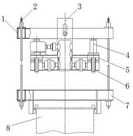
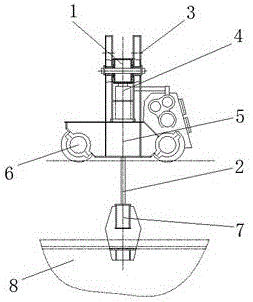
Cantilever beam lifting mechanism used in hole passing process of lower guide beam of moving mould base
A technology for moving formwork and cantilever beams, which is applied in erecting/assembling bridges, bridges, bridge construction, etc. It can solve the problems of short moving distance and lifting distance, increased risk, vertical vibration and circumferential swing of the lower guide beam, etc. To meet the needs of safety and convenience, reduce the up and down vibration and circumferential swing, and increase the rigidity
- Summary
- Abstract
- Description
- Claims
- Application Information
AI Technical Summary
Problems solved by technology
Method used
Image

Examples
Embodiment Construction
[0018] The technical solutions in the embodiments of the present invention are clearly and completely described below in conjunction with the accompanying drawings in the embodiments of the present invention. Obviously, the described embodiments are only part of the embodiments of the present invention, not all of them. Based on the embodiments of the present invention, all other embodiments obtained by persons of ordinary skill in the art without making creative efforts belong to the protection scope of the present invention.
[0019] In the following description, a lot of specific details are set forth in order to fully understand the present invention, but the present invention can also be implemented in other ways different from those described here, and those skilled in the art can do it without departing from the meaning of the present invention. By analogy, the present invention is therefore not limited to the specific examples disclosed below.
[0020] Such as Figure...
PUM
 Abstract
Description
Claims
Application Information